The idea: reuse channels far away, hand the call over at the edge
A mobile operator has only a few radio channels, but millions of calls. The trick is to cover the land with small cells, each with its own base station, and to use the same channels again in cells that are far enough apart. Their signals have faded so much on the way that they barely disturb each other. This is frequency reuse.
A phone on a call does not stay in one cell. When it drives away from its base station, the signal gets weaker and the next cell's signal gets stronger. At some point the network moves the call to the new cell: a handover. Doing that at the right place is the second half of this page.
On the left of the canvas, pick N and press Show Reuse. On the right, pick a hysteresis, a time-to-trigger and a road, and press Drive.
Clusters and the co-channel distance
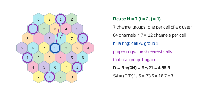
The operator splits its channels into N groups. A cluster is N neighbouring cells, each with a different group, so one cluster uses every channel once. The same pattern repeats over the map. Cells with the same group are co-channel cells.
On a hexagon grid, a pattern only tiles if N = i² + ij + j² for whole numbers i and j: 1, 3, 4, 7, 9, 12, … To find the nearest co-channel cell, go i cells in a straight line, turn 60°, and go j more. The distance between their centres is
where R is the cell radius (centre to corner). The page has 84 channels in total (Demo 1, Demo 2):
| N | i, j | channels per cell | D / R | S/I |
|---|---|---|---|---|
| 3 | 1, 1 | 84 / 3 = 28 | 3.00 | 13.5 = 11.3 dB |
| 4 | 2, 0 | 84 / 4 = 21 | 3.46 | 24 = 13.8 dB |
| 7 | 2, 1 | 84 / 7 = 12 | 4.58 | 73.5 = 18.7 dB |
Bigger N: less interference, fewer channels
A phone at the edge of its cell is R from its own base station and about D from each co-channel base station. Received power falls with distance to the power n, the path-loss exponent (2 in free space, about 4 on the ground). With the 6 nearest co-channel cells all sending, the signal-to-interference ratio is about
Old analog AMPS needed about 18 dB for good voice, so it used N = 7. Digital GSM copes with about 9 dB, so N = 3 or 4 works and gives each cell more channels. It is a trade: a bigger N makes the signal cleaner, but each cell gets fewer channels, so it can carry fewer calls at once.
Two curves cross at the cell edge
On the drive, base stations A and B stand 2 km apart. The page uses the log-distance path loss model with the same exponent 4:
So A is −79.1 dBm at 300 m and −100 dBm at 1000 m, where it equals B. The phone measures both cells every second (LTE calls this RSRP) and the call drops if the serving cell falls below −110 dBm. On the city road, buildings add a fixed wobble of a few dB (shadowing). At the street corner, a building hides A after 1000 m and its signal falls fast.
Hysteresis and time-to-trigger
If the network switched the moment B got stronger, a phone near the edge would switch back and forth all the time. So LTE uses event A3: the phone reports only when
- the neighbour is better than the serving cell by a margin, the hysteresis
H (LTE splits it into
a3-Offsetandhysteresis; the page adds them), and - that has stayed true for the whole time-to-trigger (TTT,
timeToTrigger, 0 to 5120 ms). If the condition breaks, the timer starts over.
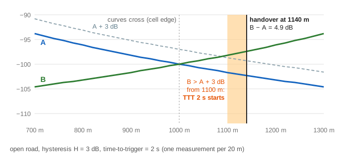
On the open road with H = 3 dB and TTT = 2 s, B passes A + 3 dB at 1100 m, and the handover fires at 1140 m, when B is 4.9 dB stronger (Demo 3). The orange strip under the chart shows where the condition holds.
The five handover messages
| # | Message | From → to | What it says |
|---|---|---|---|
| 1 | Measurement Report | phone → A | A3 is met: here are both signal levels |
| 2 | Handover Request | A → B (X2 link) | please take this call |
| 3 | Request Ack | B → A | yes, a channel is reserved |
| 4 | Handover Command | A → phone | go to B, use this channel |
| 5 | Access + Confirm | phone → B | I am here (random access, then RRC Reconfiguration Complete) |
The serving cell decides, not the phone. Because A and B use different channel groups, the phone must leave A's channel before it can use B's: a hard handover (break before make), as in GSM and LTE.
Ping-pong and dropped calls
The two settings pull in opposite directions:
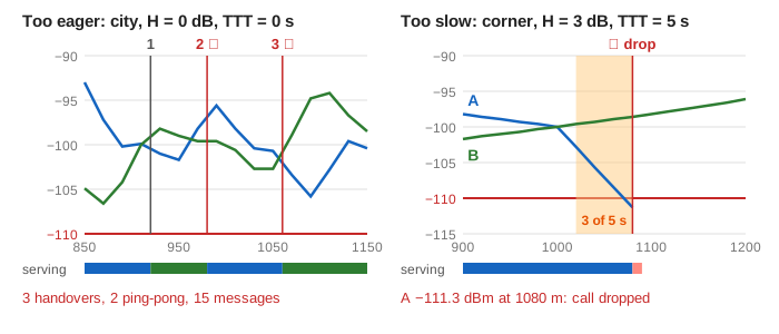
- Too eager → ping-pong. In the city with H = 0 and TTT = 0, the shadowing makes B and A swap places three times: handovers at 920 m (A → B), 980 m (back to A) and 1060 m (to B again). Two of them are ping-pongs (back to the cell just left within 10 s), and the drive costs 15 messages instead of 5 (Demo 4). With 3 dB and 2 s, the short peaks are filtered out and one handover happens at 1120 m (Demo 5).
- Too slow → dropped call. At the street corner A falls 10 dB in 80 m. With the same 3 dB but TTT = 5 s, the condition starts at 1020 m, but at 1080 m A is −111.3 dBm, below −110, and the call drops 3 s into the 5 s timer (Demo 6). With TTT = 2 s, the handover fires at 1060 m, just in time (Demo 7).
No setting is best everywhere. Real networks tune H and TTT per cell, and shorten TTT for fast phones (speed-dependent scaling).
See also Wi-Fi CSMA/CA for how many devices share one channel inside a single cell, and A Dipole Antenna for how the radio signal is sent and why it weakens with distance.
What the page leaves out
- Real cell shapes (not hexagons), sectors with directional antennas, cell splitting and small cells; the 84 channels are a toy number.
- Fast fading, noise, the second ring of interferers, and real link budgets. The shadowing is a fixed curve, not random.
- The layer-3 filter that smooths measurements, RSRQ and SINR, events A1, A2, A4 and A5, and the T310 timer before a radio link failure is declared.
- LTE and 5G mostly reuse every frequency in every cell (N = 1) and handle interference with scheduling and coordination; soft handover in CDMA/UMTS (make before break); handover to another radio technology; and what happens when the target cell has no free channel.