The idea: each layer adds a header, each device opens only what it needs
Networking software is split into layers. Each layer solves one problem and uses the layer below as a pipe: the application only writes bytes into a socket, TCP makes those bytes reliable, IP gets a packet across many networks, Ethernet gets a frame across one cable, and the physical layer turns it into signals.
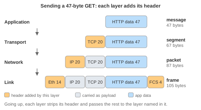
On the way down, each layer puts its own header in front of what it got from above and treats that as an
opaque payload. This is encapsulation. On the way up, each layer checks and removes its header and uses one
field of it to decide which layer gets the rest. The page follows a 47-byte GET from a laptop at home to a web
server and back, and shows the packet as a row of coloured blocks that grows and shrinks. Demo: 1. HTTP GET.
The TCP/IP layers and the OSI model
The OSI model has seven layers. The Internet actually uses the TCP/IP model, which folds OSI's session and presentation layers into the application (TLS and HTTP do that work themselves). The page draws the five-layer version, keeping link and physical apart.
| TCP/IP layer | OSI | Unit (PDU) | Examples | Address it uses |
|---|---|---|---|---|
| Application | 7 application, 6 presentation, 5 session | data / message | HTTP, DNS, TLS, SSH | names, URLs |
| Transport | 4 | segment (TCP), datagram (UDP) | TCP, UDP, QUIC | port: which process |
| Network (Internet) | 3 | packet | IPv4, IPv6, ICMP | IP address: which host, end to end |
| Link | 2 | frame | Ethernet, Wi-Fi, ARP | MAC address: which NIC on this link |
| Physical | 1 | bits | copper, fibre, radio | — |
Encapsulation, with byte counts
The request GET /index.html HTTP/1.1 + Host: example.com + an empty line is 47 bytes. TCP adds 20
(a 67-byte segment), IPv4 adds 20 (an 87-byte packet), Ethernet adds a 14-byte header and a
4-byte FCS trailer (a 105-byte frame). On the wire there are also 8 bytes of preamble and a
12-byte gap. Headers here have no options; real TCP segments usually carry 12 more bytes of timestamps.
Ethernet needs at least 46 bytes of payload, so small packets are padded: an ARP message (28 B) or a bare TCP RST (40 B) still makes a 64-byte frame. Demos 3 and 7.
Three addresses, three scopes
MAC addresses only mean something on one link. The laptop's frame is addressed to the home router's MAC, not the server's, and every router builds a brand-new Ethernet header for the next link. IP addresses stay the same from end to end: the laptop's route lookup only picks the next hop (192.168.1.1), whose MAC goes into the frame, while the IP header keeps saying 93.184.216.34. Ports pick the socket, and so the process, inside a host.
The one exception is NAT. The home router rewrites the private source 192.168.1.10:51514 into its public 203.0.113.7:40001 and keeps a table so it can reverse the change for replies. The server only ever sees the router's address. Because the TCP/UDP checksum covers the IP addresses, NAT must fix it too. Demo: 2. The reply comes back. The translation table, several hosts sharing the address, timeouts, port forwarding and hole punching are on How NAT Shares One Public Address.
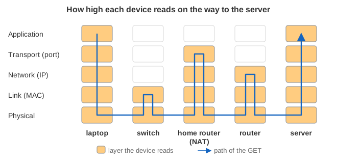
What each device opens
| Device | Highest layer it reads | What it changes |
|---|---|---|
| Switch | Link (L2) | Nothing. It learns which MAC is on which port from source addresses, and floods frames to unknown or broadcast destinations. |
| Router | Network (L3) | Strips the frame, decrements the TTL, recomputes the IP header checksum, builds a new frame. |
| Home router (NAT) | Transport ports (L4) | As a router, plus source/destination IP and port and the TCP/UDP checksum. It also runs its own DNS forwarder and DHCP. |
| Hosts | All of them | Add every header on the way down and remove every header on the way up. |
Going up: demultiplexing
Every header names the protocol of its payload. The link layer reads EtherType (0x0800 IPv4, 0x0806 ARP, 0x86DD IPv6), IP reads the protocol number (6 TCP, 17 UDP, 1 ICMP), and TCP/UDP read the destination port (80 nginx, 53 DNS). If no socket has the port, TCP answers a SYN with RST and UDP gets an ICMP port unreachable. Demo: 7. Port closed.
ARP: the glue between IP and Ethernet
To send to the next hop, the laptop needs its MAC address. If the ARP cache has no entry, the IP packet
waits and ARP broadcasts "who has 192.168.1.1?" to ff:ff:ff:ff:ff:ff. The switch floods the broadcast, the router
answers with a unicast reply, and both sides cache the pair. DNS query tab, Demo: ARP, then DNS.
MTU, MSS and fragmentation
An Ethernet frame carries at most 1500 bytes of IP packet (the MTU). TCP never gives IP more than fits: its MSS is 1500 − 20 − 20 = 1460, so a 3000-byte response becomes segments of 1460 + 1460 + 80 bytes. Demo: 4. UDP sends each message whole, so a 2000-byte datagram (2028 bytes with headers) is split by IP into fragments. They share an ID, have offsets 0 and 185 (in 8-byte units) and the More Fragments flag on the first. The receiver reassembles them before UDP sees anything. If one fragment is lost, the whole datagram is lost. UDP 2000 B tab, Demo: fragmentation.
TTL, ICMP and traceroute
Every router decrements the TTL, and one that would decrement it to 0 drops the packet and sends ICMP Time Exceeded back. That message quotes the dropped packet's header and first 8 bytes. It stops routing loops, and traceroute uses it: probes with TTL 1, 2, 3, … each die one hop further and reveal that router's address. The last probe reaches the server and gets "port unreachable". Even the ICMP messages pass back through NAT, which matches them using the quoted header. traceroute tab, Demo: TTL 1, 2, 3.
Where errors are caught
| Layer | Check | On failure |
|---|---|---|
| Link | FCS (CRC-32) on each hop | frame dropped silently |
| Network | header checksum, TTL | dropped; ICMP for TTL |
| Transport | TCP/UDP checksum; TCP sequence numbers and ACKs | TCP retransmits after the RTO; UDP does nothing |
A bit flipped on the LAN is caught by the switch's FCS check and the frame disappears. Only TCP, end to end, notices the missing ACK and sends the same bytes again. Demo: 8. Bit flip on the LAN.
See also How an HTTP Connection Is Established (the TCP handshake this page assumes), How a DNS Name Is Resolved, How an HTTPS Connection Is Established, TCP Congestion Control, TCP vs UDP (the two transport protocols side by side) and HTTP/1.1 vs HTTP/2 vs HTTP/3.
What the page leaves out
IPv6 (no fragmentation by routers, no ARP but Neighbor Discovery), Wi-Fi's 802.11 framing (a laptop is usually on Wi-Fi, whose frames carry three or four MAC addresses), VLAN tags, TCP options (MSS, window scaling, SACK and timestamps are all real and all left out), the ACKs the receivers send, TLS between TCP and HTTP, how routers learn routes (BGP, OSPF), path MTU discovery, and NIC offloads, which in practice let the kernel hand the NIC 64 KB "segments" to cut up. The TCP and UDP checksums and the FCS are stand-in hashes; the IPv4 header checksum is computed for real.