The idea: let the device move the data
A packet has to get from the network card into RAM, where the kernel and the program can use it. There are two ways to do that.
- Programmed I/O (PIO). The card keeps the packet in its own small buffer and raises an
interrupt. The CPU then reads it out through an I/O port, one 16-bit word at a time
(
rep insw), and stores each word in RAM. Every byte passes through a CPU register. While it copies, the CPU does nothing else. - Direct memory access (DMA). The card is a bus master: it can send its own read and write requests over PCIe to RAM. The driver only tells it where to put packets. The card writes the data itself while the CPU runs other programs, and it raises one interrupt when there is something to look at.
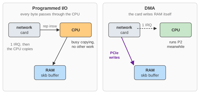
On the canvas, P1 is a UDP server sleeping in recvfrom(), and P2 is a program that just
wants the CPU. The P2 ticks counter shows how much CPU time the I/O leaves for real work.
(Demo 1 and Demo 3.)
| PIO card | DMA card | |
|---|---|---|
| who moves the bytes | the CPU, word by word | the card, over PCIe |
| CPU cost per packet | grows with the packet size | a small fixed cost (descriptor, skb, refill) |
| interrupts | at least one per batch the CPU copies | one per batch, and NAPI polls the rest |
| buffer space | a few packets on the card | a ring of buffers in RAM (256 to 4096 in real NICs) |
| new problems | none: the CPU sees everything | addresses, cache coherency, protection |
Descriptor rings: head, tail and the DD bit
The driver and the card share a ring of descriptors in RAM. An RX descriptor holds the bus address of an empty buffer, and space for the card to report the length and a status. The two sides take turns:
- The card owns the descriptors from the head (
RDH, which only the card moves) up to just before the tail (RDT, which only the driver moves). On the canvas these are purple. - For each packet the card fetches the descriptor at the head, writes the data into that buffer, then writes the descriptor back with DD (descriptor done) set and moves the head on (yellow).
- The driver walks the ring from where it stopped, takes every descriptor with DD, gives it a fresh buffer, and then moves the tail with one register write. That write is the doorbell.
- If the head catches up with the tail, the card has no buffer left and must drop packets
(
rx_missed_errors, Demo 6). One slot always stays empty, so that "head == tail" can only mean "nothing for the card".
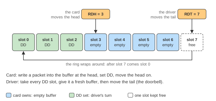
This pattern is everywhere: NVMe submission and completion queues, virtio virtqueues and io_uring all work the same way. A queue in shared memory has a producer index and a consumer index, and a doorbell says "there is new work".
Every step of one received packet
(Demo 2.) Purple boxes on the timeline are PCIe transactions made by the card itself.
| # | who | what |
|---|---|---|
| 1 | wire → NIC | The packet lands in the card's small on-chip FIFO. |
| 2 | NIC (DMA read) | It fetches the descriptor at RDH and gets the buffer address. |
| 3 | NIC (DMA write) | It writes the packet into the buffer, one 64-byte line per tick here, through the IOMMU. |
| 4 | NIC (DMA write) | It writes back the descriptor: length, DD. RDH moves on and the RX cause is set in ICR. |
| 5 | NIC → CPU | MSI-X: a DMA write to address 0xfee00000 that the root complex turns into an interrupt. |
| 6 | CPU, hard IRQ | The handler masks the NIC interrupt and calls napi_schedule(). Nothing else. |
| 7 | CPU, NAPI poll | For each descriptor with DD: dma_unmap_single(), build an skb around the page (no copy), queue it on the socket, wake P1. |
| 8 | CPU, NAPI poll | Refill: a new or recycled page, dma_map_single(), its address into the descriptor. Then one MMIO write to RDT. |
| 9 | CPU, NAPI poll | Fewer packets than the budget: napi_complete_done() and the interrupt is unmasked. |
| 10 | P1 | recvfrom() copies the 256 bytes to ubuf (copy_to_user) and returns. |
Transmit is the mirror image (Demo 4). sendto() copies the data into an skb,
the driver maps it (DMA_TO_DEVICE), writes a TX descriptor and rings TDT. The
card reads the descriptor and the data, sends the packet, and writes back DD. In the next poll the driver
unmaps the buffer and frees it.
Interrupts and NAPI
At a million packets per second, one interrupt per packet would use up the whole CPU. This is
called receive livelock: the CPU spends all its time entering and leaving interrupt
handlers, and the packets it accepts are never processed. Linux avoids it with
NAPI. The first packet raises an interrupt. The handler masks further interrupts
from the card and schedules a poll, which handles up to a budget of packets
per round (64 by default; 4 on the canvas). While packets keep coming, the poll keeps running and
there are no more interrupts. When a round finds less work than the budget, the driver unmasks the
interrupt again. The card also has its own limit, interrupt moderation
(ethtool -C eth0 rx-usecs 50): it waits at least that long between two interrupts
(here ITR = 18 ticks). A PIO card has neither, and the copying itself is what
overloads the CPU (Demo 3).
Devices don't use virtual addresses: the DMA API
A buffer that is contiguous for the program is a set of scattered physical pages, and a device knows nothing about page tables. So the driver must turn a buffer into a bus address, and in Linux this always goes through the DMA API:
dma_alloc_coherent(): memory shared with the device for a long time, set up so the CPU and the device always see the same data. The descriptor rings live here.dma_map_single()/dma_map_sg(): streaming mappings for one transfer, with a direction (DMA_FROM_DEVICE,DMA_TO_DEVICE). This returns the address to put in the descriptor, and it does any cache work or bouncing that is needed.dma_unmap_*anddma_sync_single_for_cpu/for_deviceundo it or hand the buffer over again.
The rule is ownership. Between map and unmap, the buffer belongs to the device and the
CPU must not touch it. After unmap (or sync_for_cpu) it belongs to the CPU again.
The IOMMU: translation and protection
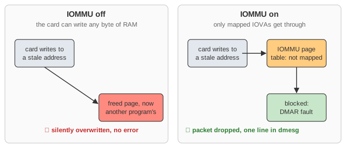
The IOMMU (Intel VT-d, AMD-Vi, Arm SMMU) sits in the PCIe root complex. It does for devices what the MMU does for programs: the device uses IO virtual addresses (IOVAs), and the IOMMU's page table turns them into physical addresses. It also checks the permission (read-only for a TX buffer, write for an RX buffer). An access that is not mapped is blocked and logged as a DMAR fault.
Without an IOMMU, a device can read or write any byte of RAM. A driver bug (a descriptor that still
holds the address of a freed page) or a malicious device then overwrites another program's memory
without any error (Demo 7). With the IOMMU, the same bug is a dropped packet and a line in
dmesg (Demo 8). The IOMMU is also what lets a VM own a real device safely (VFIO),
and what stops DMA attacks through Thunderbolt or FireWire ports.
MMIO writes from the CPU to the card's registers (RDT, TDT, IMS)
go the other way and do not pass through the IOMMU.
Cache coherency
The CPU reads and writes through its cache; the card reads and writes RAM. They can disagree in two ways:
- Stale line: the CPU has an old copy of a line in its cache (S) and the card writes new data to RAM. The CPU keeps reading the old copy.
- Dirty line: the CPU wrote new data that is still only in its cache (M). The card reads RAM and gets the old bytes.
On x86 the hardware solves this: every DMA access is snooped, so a
device write invalidates cached copies and a device read gets dirty data from the cache. Intel DDIO
even writes incoming packets straight into the last-level cache. On many ARM and other
embedded SoCs, DMA is not coherent, and the DMA API does the work in software:
dma_map(DMA_TO_DEVICE) cleans (writes back) the cache, and
dma_map/unmap(DMA_FROM_DEVICE) invalidates it.
A driver that skips this, for example by recycling pages with DMA_ATTR_SKIP_CPU_SYNC and
forgetting dma_sync_single_for_cpu(), works on x86 and breaks on ARM: P1 receives the
previous packet that was in the same page (Demo 5). Switch the CPU to ARM with the driver
correct to see the invalidates, or press P1: sendto with the bug to send old bytes.
DMA masks and bounce buffers
Some devices can only produce 32-bit addresses (dma_set_mask(dev, DMA_BIT_MASK(32))), so
they cannot reach RAM above 4 GiB, where the buffer pages here live. Without an IOMMU, Linux uses
swiotlb: it gives the device a bounce slot below 4 GiB, and on unmap the
CPU copies the data to the real buffer (on transmit, before the device reads it). That copy is
exactly the work DMA was supposed to save. With an IOMMU, the IOVA is simply chosen below 4 GiB
and mapped to the high page, so there is no copy. Try DMA mask = 32-bit with the IOMMU off, then on.
(Encrypted VMs, SEV and TDX, bounce all DMA through swiotlb for a different reason: the device may
not read private guest memory.)
Zero copy
DMA removes the copy between the device and RAM. One copy is left: recvfrom() and
sendto() copy between the kernel's skb and the program's buffer. sendfile()
and splice() skip it for files, MSG_ZEROCOPY lets the card read user pages
directly, and AF_XDP or DPDK let a program own the RX ring's buffers itself.
How to see it on a real system
ethtool -g eth0                      # RX/TX ring sizes
ethtool -S eth0 | grep -i -e miss -e drop -e err    # rx_missed_errors etc.
ethtool -c eth0                      # interrupt moderation (rx-usecs)
grep eth0 /proc/interrupts           # one MSI-X vector per queue, counts per CPU
dmesg | grep -i -e DMAR -e iommu -e swiotlb
ls /sys/kernel/iommu_groups/*/devices
What the page leaves out
- One RX queue, one TX queue and one CPU. Real NICs have many queues, spread over CPUs by RSS, each with its own MSI-X vector.
- Sizes are scaled down: 256-byte packets, a ring of 8, a budget of 4. Real PCIe writes carry 128 to 512 bytes, and real RX buffers are 2 KiB or a page.
- Checksum offload, TSO/GRO, header split, PCIe ordering and flow-control rules, and the IOTLB cache and its invalidation are not drawn.
- The CPU cache never evicts anything here, as if it were large. Real drivers usually use
page_pool, which keeps recycled pages mapped. - The old ISA 8237 DMA controller, a third-party "DMA engine" that copied for a device, and peer-to-peer DMA between devices.
See also Linux Virtual Memory (the MMU side of address translation), CPU Cache (coherency and MESI), Linux Context Switch (what happens when P1 sleeps and wakes), nginx Proxy Request: Memory and System Calls (the copies between user and kernel space), Linux epoll and TCP vs UDP.