The idea: clip against one edge at a time
Only the part of a shape inside the window (the visible rectangle) should be drawn. Clipping cuts away the rest before the shape is filled. The page uses the window 4 ≤ x ≤ 16, 3 ≤ y ≤ 10 on a whole-number grid with y going up.
A window has four edges, and each edge is a straight line that splits the plane into a kept side and a thrown-away side. Clipping against one line is easy. So both methods on this page clip against one window edge at a time, and the result of one edge goes on to the next.
Outcodes: Cohen–Sutherland for a line
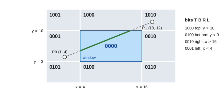
The Cohen–Sutherland method gives every endpoint a 4-bit outcode, one bit per window edge, in the order top, bottom, right, left (TBRL). A bit is 1 when the point is outside that edge: top 1000 (y > 10), bottom 0100 (y < 3), right 0010 (x > 16), left 0001 (x < 4). The window itself is 0000, and the eight regions around it get the codes in the figure.
Two outcodes give quick answers with plain bit operations:
- OR = 0000: both ends are inside, so the whole line is inside. Draw it (trivial accept).
- AND ≠ 0000: both ends are outside the same edge, so the whole line is outside. Drop it (trivial reject).
- Otherwise: take an endpoint that is outside, take its first set bit, cut the line at that edge, move the endpoint to the cut and test again.
The line from P0 (1, 4) to P1 (18, 12) has codes 0001 and 1010. Pass 1 cuts P0 at x = 4: y = 4 + 8 · 3/17 = 5.41. Pass 2 takes P1. Its code 1010 has two bits; top comes first, so it is cut at y = 10, at (13.75, 10), which is already inside. Pass 3 sees OR = 0000 and accepts (Demo: Cohen–Sutherland, a line through the window). The cut points use y = y0 + (y1 − y0)·(x − x0)/(x1 − x0) for a vertical edge and the same with x and y swapped for a horizontal one.
AND = 0000 does not mean the line meets the window. The line from (1, 9) to (7, 13) has codes 0001 and 1000. Its cut at x = 4 lands at (4, 11), code 1000, above the window. Now AND = 1000 and the line is rejected (Demo: a line past a corner). A line wholly above the window is rejected in pass 1 with no cut, and a line wholly inside is accepted in pass 1 (Demo: trivial reject, then trivial accept).
Sutherland–Hodgman: the four cases
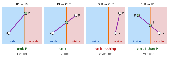
A polygon can't be clipped one line at a time: the cut pieces must still join into a closed shape. Sutherland–Hodgman walks round the polygon for one window edge. For each edge from S (the vertex before) to P, it writes 0, 1 or 2 points to an output list. A point on the clip line counts as inside.
| S | P | Emit | Why |
|---|---|---|---|
| in | in | P | the edge stays inside |
| in | out | I | the edge leaves: keep only where it crosses |
| out | out | nothing | the edge is thrown away |
| out | in | I, then P | the edge comes back in |
The output list, read in order, is the clipped polygon. It goes in as the input for the next window edge. The page clips left, right, bottom, then top.
Four clippers in a row
The triangle A (1, 2), B (19, 6), C (7, 14) sticks out of all four edges. Each edge cuts off a corner and adds a vertex (Demo: clip a triangle against 4 edges):
| Window edge | Keep | New points | Vertices | Area |
|---|---|---|---|---|
| (start) | 3 | 96 | ||
| left | x ≥ 4 | I1 (4, 8), I2 (4, 2.67) | 4 | 88 |
| right | x ≤ 16 | I3 (16, 5.33), I4 (16, 8) | 5 | 84 |
| bottom | y ≥ 3 | I5 (4, 3), I6 (5.5, 3) | 6 | 83.75 |
| top | y ≤ 10 | I7 (5, 10), I8 (13, 10) | 7 | 67.75 |
The triangle ends as the 7-gon I7 I1 I5 I6 I3 I4 I8. In general each window edge can add one vertex, so a convex n-gon can come out with up to n + 4 vertices. The points are not lost along the way: I2 (4, 2.67) is a new vertex after the left edge, and the bottom edge then throws it away.
A shape that covers the whole window ends as the window itself. The square (2, 1) to (18, 12) keeps 4 vertices through every edge, and its area goes 176 → 154 → 132 → 108 → 84 = 12 × 7. None of its own corners survive: the output is the four window corners (Demo: a polygon around the whole window).
Concave shapes: the degenerate edge
The concave ∩ shape has two legs that join above the window. The left edge cuts off its left side (74 → 58). The top edge then cuts off the bar that joins the legs, and here all four cases happen in one pass. The visible part is two separate rectangles, but Sutherland–Hodgman always outputs one list: I3 I1 B I4 I5 E F I6, 8 vertices (Demo: a concave shape leaves a degenerate edge along the top).
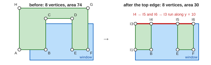
The edges I4 (7, 10) → I5 (12, 10) and I6 (15, 10) → I3 (4, 10) both lie on the window border and overlap from x = 7 to x = 12. They enclose no area: they are degenerate edges. The area is still right, 30 = 15 + 15. A filled polygon looks right too, because a zero-width sliver fills no pixel centre. But a program that draws the outline shows a line along the top of the window that is not in the shape. Weiler–Atherton or Vatti clipping split such a shape into its real pieces.
Back faces: winding order
Before clipping, the page computes the signed area with the shoelace formula:
a = ½ · Σ (x_i · y_(i+1) − x_(i+1) · y_i)
a > 0: vertices go counter-clockwise      a < 0: clockwise
For the triangle the three terms are −32, +224 and 0, so a = +96: counter-clockwise. In OpenGL, glFrontFace(GL_CCW) (the default) makes counter-clockwise polygons front faces. With glEnable(GL_CULL_FACE) and glCullFace(GL_BACK) the GPU drops every back face: on a closed solid those are the sides turned away from the camera, hidden anyway. The triangle (6, 4), (9, 9), (14, 5) lies wholly inside the window, but its terms 18, −81 and 26 give a = −18.5. It is clockwise, so it is culled and never clipped or filled (Demo: a clockwise triangle is a back face).
Clipping keeps the winding. Each output list visits the kept points in the same order round the shape, so the sign never flips: the triangle is +96 before and +67.75 after, the ∩ shape +74 and +30. That is why a GPU can test the winding after clipping, on the final screen positions, as the OpenGL spec does.
Where it sits in the pipeline
A GPU clips triangles in 4D clip space before the divide by w, against planes like −w ≤ x ≤ w; the near plane is shown in The Graphics Pipeline. The idea is the same as here, one plane at a time with the same four cases. A convex clipped polygon is cut back into a fan of triangles, and an n-gon gives n − 2 of them, as in Ear Clipping. Each triangle is then filled pixel by pixel, see Rasterization: Edge Functions and the Z-Buffer. A clipped line is drawn with Bresenham's Line Algorithm.
What the page leaves out
The page leaves out clipping in homogeneous coordinates and the near and far planes, guard-band clipping (GPUs mostly let the rasterizer skip pixels outside the screen), the Liang–Barsky and Cyrus–Beck line clippers that work with the parameter t, clipping against a window that is any convex polygon, Weiler–Atherton and Vatti clipping for concave windows and for splitting the result into pieces, polygons with holes, rounding errors from floating-point cut points, and front-face culling or culling turned off.