The idea: one object's life, one process's steps
A sequence diagram shows one run of a scenario. Two other UML diagrams show behaviour in a different way. A state machine diagram shows the whole life of one object: the states it can be in, and which events move it from one state to the next. An activity diagram shows the steps of a process: which action comes after which, which ones run at the same time, and who does each one.
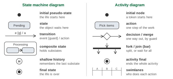
Both diagrams are easiest to read with a token: a marker that shows where you are. On the left of the canvas the token sits in the current state of one Order. It moves only when an event arrives. On the right a token walks through the order process, one arrow per tick. The order costs 55.
States, events, guards and actions
A state is a situation the object stays in for a while, such as Pending (waiting to be paid). An event is something that happens to the object, such as pay(55) or cancel. A transition is an arrow from one state to another. Its label has up to three parts:
| Part | Example | Meaning |
|---|---|---|
| event | pay(amt) | what the transition waits for |
| [guard] | [amt ≥ 55] | a condition; the arrow fires only if it is true |
| / action | / sendReceipt() | what runs while the arrow is taken |
Only the current state reacts. If no arrow for the event leaves the current state, the event is ignored: nothing runs and the state stays the same. ship while the order is still in Picking does nothing, because only Packed has a ship arrow. Demo 3: ship while picking is ignored.
A guard is checked before anything else. pay(40) arrives at Pending, the guard [40 ≥ 55] is false, and the transition does not fire at all: no exit, no sendReceipt(), no entry. Then pay(55) passes. Demo 2: a guard says no to pay(40).
Entry and exit actions: the order of a transition
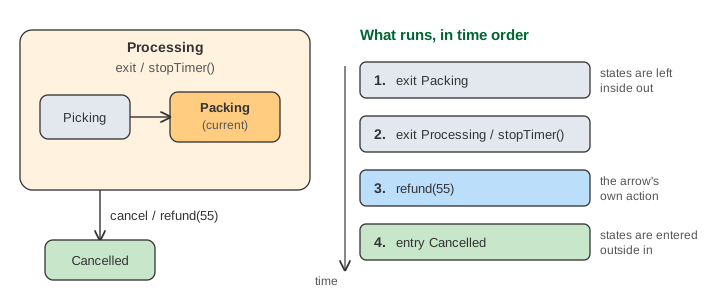
A state can have an entry action (it runs every time the state is entered) and an exit action (every time it is left). They are written inside the box: entry / printLabel(). When a transition fires, things happen in a fixed order:
- the exit actions of the states being left, the innermost state first;
- the transition's own action;
- the entry actions of the states being entered, the outermost state first.
The log under the state machine lists, in order, what the last event ran. Demo 4: cancel while packing gives four lines: exit Packing, exit Processing / stopTimer(), the action refund(55), entry Cancelled.
Composite states and history
A composite state holds smaller states, its substates. Processing holds Picking, Packing and Packed. While the order is in Packing, it is in Processing too, so both are shaded. When the order enters Processing, the small black dot inside it, its own initial pseudo-state, leads to Picking. Demo 1: happy path, pay to delivery fires five transitions: pay(55), picked, packed, ship and deliver.
An arrow that starts on the border of the composite state applies to every substate. That saves drawing cancel and hold three times each. An arrow that starts at a substate, like ship from Packed, applies only there.
The circle with an H is a shallow history pseudo-state. When the order goes to OnHold, Processing remembers which substate was active. resume points at the H, so the order goes back to that substate instead of starting again at Picking. Entry actions still run on the way in: startTimer() and printLabel() run a second time. Demo 5: hold and resume, history returns to Packing.
Activity diagrams: tokens, decisions, fork and join
An activity diagram is read by moving tokens along its arrows. A rounded box is an action, one step of the work. A token on the initial node starts the activity; when any token reaches the activity final node, the whole activity ends.
- A decision (diamond) has one arrow in and several out, each with a guard. The token takes the one arrow whose guard is true. A merge (also a diamond) joins such branches again. Demo 7: activity, decision takes [else] runs only 3 actions in 5 ticks.
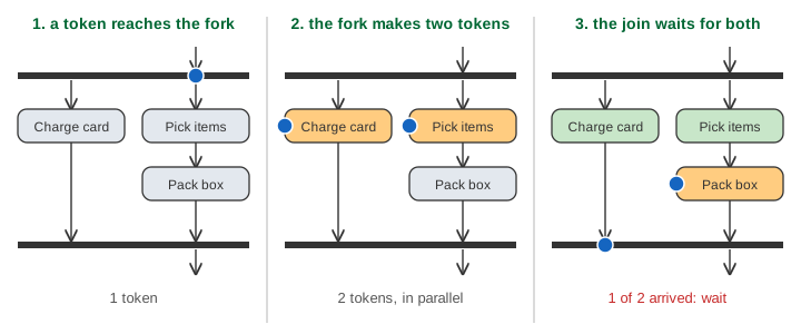
- A fork (thick bar) has one arrow in and several out. One token comes in and one leaves on every outgoing arrow, so the branches run in parallel.
- A join (thick bar) has several arrows in and one out. It waits until a token has arrived on every incoming arrow, then sends one token on.
In Demo 6: activity, fork and join (in stock), the fork makes 2 tokens. Charge card takes one tick and Pick items then Pack box take two, so the Charge card token waits 1 tick at the join. The walk takes 10 ticks and runs 7 actions.
Swimlanes
The columns Customer, Shop and Warehouse are swimlanes (UML calls them partitions). Each action sits in the lane of whoever does it. An arrow that crosses a lane line is a hand-over: after Place order the work moves from the customer to the warehouse. Lanes make it easy to see who is busy and where the waiting happens.
State machine or activity diagram?
| State machine diagram | Activity diagram | |
|---|---|---|
| Describes | one object over its whole life | a process, a use case or an algorithm |
| Boxes are | states: the object waits there | actions: work is done there |
| Arrows fire when | an event arrives (and the guard holds) | the action before them is done |
| Parallel work | not shown here (orthogonal regions) | fork and join |
| Who does it | not shown | swimlanes |
The two describe the same order from two sides. The state machine says what the Order may do next, whatever happens; the activity diagram says what the people and systems do, in which order. To turn a state machine into code, see The State Pattern, which uses a similar order life cycle. The same idea in hardware is in Finite State Machines, and an operating system's process states are in Process Lifecycle. For the messages between objects in one run, see UML Sequence Diagram.
See also UML class diagrams for the classes, associations and multiplicities that the states and activities here belong to.
What the page leaves out
The canvas draws states and actions as square boxes and every arrowhead filled; UML draws them with rounded corners and open arrowheads. The state machine leaves out orthogonal regions (two parts of one state active at once), deep history (H*), internal transitions and do / activities, time and change events (after(2 days), when(...)), choice and junction pseudo-states, entry and exit points, and the run-to-completion queue that holds events while a transition runs. The activity diagram leaves out object nodes and pins (data flowing between actions), flow final nodes (which end one branch, not the whole activity), signals sent and received, interruptible regions and loops drawn with a decision and a merge.