The idea: a register and two blocks of logic
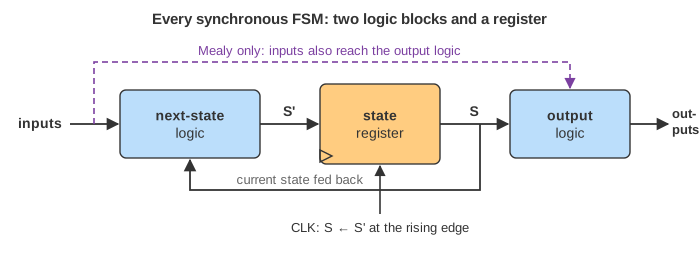
A finite state machine (FSM) is a circuit with memory that follows a fixed set of rules. Every synchronous FSM has the same three parts:
- a state register: k flip-flops on one clock, holding the current state S;
- next-state logic: combinational logic that computes the next state S' from S and the inputs;
- output logic: combinational logic that computes the outputs.
Between clock edges the two logic blocks settle. At the rising clock edge every flip-flop copies its D input to Q at the same instant, so S becomes S'. Nothing else ever changes the state. With k flip-flops the machine has at most 2k states, which is why it is called finite.
The page runs one clock cycle in three steps: the inputs arrive, the logic computes S' (the matching table row, diagram arrow and equations light up), and the clock edge loads the register. The timing diagram below the machines records CLK, the inputs, the state and the outputs of every cycle. Grey digits are inputs of the coming cycles; Toggle changes the next one.
Designing an FSM
The book designs every FSM in the same order, and the page shows all of these views of the same machine at once:
- Draw the state transition diagram: one circle per state, one arrow per transition, labelled with the input condition. The arrow marked reset shows the starting state.
- Write the state transition table: current state and inputs → next state. X means "don't care".
- Encode the states as bit patterns and rewrite the table in bits.
- Read off the next-state equations (sum of products, then simplify).
- Write the output table and the output equations.
- Draw the circuit: flip-flops plus the gates of the equations.
The page evaluates the book's equations on the encoded bits, exactly as the gates would, and uses the table only to light the row that matches. The two always agree; that is what a correct design means.
The traffic light controller
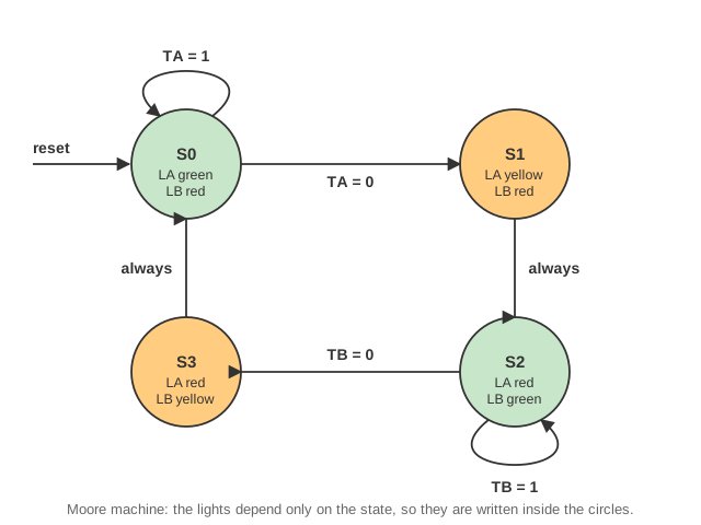
Academic Avenue and Bravado Boulevard cross. Sensors TA and TB are 1 when there are cars on each street; lights LA and LB show green, yellow or red. The controller is a Moore machine with four states:
| State | LA | LB | Next state |
|---|---|---|---|
| S0 | green | red | S0 while TA = 1, else S1 |
| S1 | yellow | red | S2 |
| S2 | red | green | S2 while TB = 1, else S3 |
| S3 | red | yellow | S0 |
With green = 00, yellow = 01, red = 10 and the binary encoding S0..S3 = 00, 01, 10, 11, the equations are (¬x is x̄, NOT x):
S1' = S1 ⊕ S0
S0' = ¬S1·¬S0·¬TA + S1·¬S0·¬TB
LA1 = S1        LA0 = ¬S1·S0
LB1 = ¬S1       LB0 = S1·S0
In Demo 1, cars on Academic keep it in S0 for three cycles, then it cycles S1, S2 (held one extra cycle by TB = 1), S3 and back to S0 at cycle 7, where TA = 1 keeps Academic green. After 8 cycles: LA was green for 4 cycles, LB for 2.
A machine does exactly what its table says, including the parts nobody wanted. In S0 the controller only looks at TA. In Demo 3 both streets are busy all the time: the FSM never leaves S0 and Bravado's light stays red for ever (starvation). Real controllers add a timer input so that green lasts at most a fixed time.
Careful with the names: S0..S3 are states, while S1 and S0 in the equations are the two bits of the state register. The book uses the same letters for both.
State encodings: binary vs one-hot
The states can be encoded in any way; the choice changes the hardware, not the behaviour.
- Binary: number the states 0, 1, 2, … and store the number in ⌈log2 N⌉ flip-flops. Fewest flip-flops; the equations come from a K-map and can be tangled.
- One-hot: one flip-flop per state, exactly one of them is 1 ("hot"). The equation of a state bit has one product term per arrow into that state, so it can be read straight off the diagram: S0' = S0·TA + S3 says "stay in S0 if TA, or come from S3". More flip-flops, but often simpler and faster logic, which is why one-hot is popular in FPGAs, where flip-flops are plentiful.
| Machine | Binary: flip-flops / next-state literals | One-hot: flip-flops / next-state literals |
|---|---|---|
| Traffic light (4 states) | 2 / 8 | 4 / 10 |
| Moore 01 recognizer (3 states) | 2 / 3 | 3 / 7 |
| Mealy 01 recognizer (2 states) | 1 / 1 | 2 / 2 |
| Lights FSM with parade input M | 2 / 9 | 4 / 13 |
Demo 2 runs the traffic of Demo 1 with one-hot encoding: the same states and lights in every cycle, with four flip-flops instead of two. Switching the encoding menu at any moment keeps the current state and only changes its bits. In these small machines binary needs fewer literals; the advantage of one-hot shows in larger machines, where binary equations grow with every state bit and one-hot equations stay one term per arrow.
A binary code can have unused patterns: the Moore 01 recognizer has three states in two bits, so 11 is never used. A one-hot register has 2N − N unused patterns. Reset must put the machine in a legal state, and a glitch that ever reached an unused pattern would leave the machine somewhere the design never considered.
Moore and Mealy machines
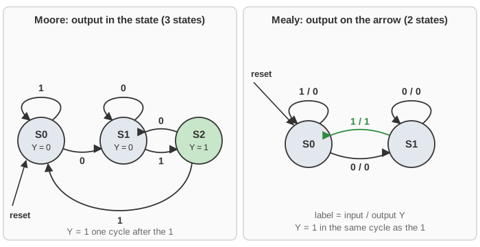
A Moore machine's outputs depend only on the current state, so they are written inside the state circles and change only just after a clock edge. A Mealy machine's outputs depend on the state and the inputs, so they are written on the arrows (input / output) and can change in the middle of a cycle, as soon as an input changes.
The book's example is a snail crawling along a tape of 0s and 1s that smiles (Y = 1) when the last two digits are 0 then 1. The Moore machine needs three states: S0 (nothing useful seen), S1 (last digit 0) and S2 (just saw 0 1, Y = 1). The Mealy machine needs only two, S0 and S1, because the output is produced by the arrow "1 / 1" out of S1, in the same cycle as the 1.
| Input A, cycles 0–9 | 0 | 1 | 0 | 1 | 1 | 0 | 0 | 1 | 1 | 1 |
|---|---|---|---|---|---|---|---|---|---|---|
| Mealy Y | 0 | 1 | 0 | 1 | 0 | 0 | 0 | 1 | 0 | 0 |
| Moore Y | 0 | 0 | 1 | 0 | 1 | 0 | 0 | 0 | 1 | 0 |
That is Demo 4: both machines find the same three matches, and the Mealy output is always one cycle earlier. Demo 5 feeds 0 1 0 1 0 1 …: the matches overlap (the 0 after a match starts the next one, S2 → S1), and with one-hot encoding the Moore machine uses three flip-flops and the Mealy machine two.
The price of the early Mealy output is that it is combinational from input to output: if A glitches, Y glitches, and a long chain of Mealy machines forms one long combinational path. A Moore output comes straight from flip-flops and is clean for the whole cycle.
Factoring: the parade mode
The city adds a parade mode: input P starts it, R ends it, and while it lasts Bravado Boulevard stays green. One FSM would need eight states: every traffic state twice, once in normal mode and once in parade mode. Factoring splits it in two smaller machines that talk through a wire:
- the mode FSM (2 states) remembers the mode and outputs M = 1 in parade mode;
- the lights FSM is the old controller with one more input: S2 holds while M + TB, and goes to S3 only when ¬M·¬TB.
Each machine is easy to check on its own, 6 states in all instead of 8, and the same 3 flip-flops in binary. In Demo 6, P arrives in cycle 1, M = 1 from cycle 2, and the lights stay in S2 for cycles 2–8 although TB = 0; R in cycle 7 releases them.
M is the output of the mode register, so it changes only at a clock edge, one cycle after P. Demo 7 shows the consequence: P arrives in cycle 2, when the lights are already in S2 with TB = 0. M is still 0 in that cycle, so the lights go to S3 and do a full round before parade mode can hold them in S2 from cycle 6. Whether that one-cycle delay matters is a design decision; an unfactored FSM could react in the same cycle.
Timing: what the clock edge does
In the timing diagram the state and Moore outputs change just after each rising edge (the clock-to-Q delay), the inputs change a little later, at any time in the cycle, and the Mealy output follows the input at once. Only the values at the rising edge matter for the next state: the flip-flops sample S' there. For that the next-state logic must have settled before the edge (the setup time); the slowest path through it sets the maximum clock frequency, as on the Sequential Logic page, which builds the flip-flops used here from gates.
An FSM is also how a processor is controlled: the multicycle MIPS processor's control unit is a Moore FSM that steps through fetch, decode, execute, memory and write-back states. The single-cycle processor needs only combinational control (The Single-Cycle MIPS Processor), and the logic blocks themselves are on the Combinational Logic page. In software, an FSM is a loop around a switch on the state; the KMP string search is a pattern-recognizing automaton like the snail, built from the pattern.
What the page leaves out
- Inputs change once per cycle, and only their values at the clock edge are used. Asynchronous inputs need a synchronizer (two flip-flops) first, or the state register can go metastable.
- No gate delays: the logic settles instantly, so there are no setup or hold violations and no glitches on the Mealy output.
- The equations are the book's hand-simplified ones; the page does not run K-map minimization or count gates, only literals.
- The timer of a real traffic controller, the eight-state unfactored parade FSM and the book's other encodings (Gray, one-cold) are not drawn.
- The register is reset asynchronously to S0 by the Reset button; reset timing is not shown.
References
Harris and Harris, Digital Design and Computer Architecture, Section 3.4: Finite State Machines (traffic light controller, state encodings, Moore and Mealy machines, factoring)