The idea: pick the next state, then find the inputs that give it
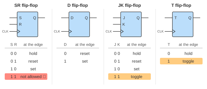
A flip-flop stores one bit, Q. It changes only at the rising edge of the clock. What it changes to depends on its inputs at that moment. Four kinds are in common use: SR, D, JK and T. Each can do some of four things at an edge: hold Q, set it to 1, reset it to 0, or toggle it.
A counter is a few flip-flops that step through a fixed list of states. To design one you work backwards. You know the next state you want. You look up which inputs make each flip-flop go there. Then you build the gates that produce those inputs from the present state.
On the canvas, pick one flip-flop in the show menu, set its inputs with the Toggle buttons and press Clock Edge. Or pick a counter, press Design Step five times, then press Clock Edge to count. Wires at 1 are blue and wires at 0 grey.
Characteristic tables: inputs give the next Q
The characteristic table of a flip-flop answers: with these inputs, what is Q after the edge? Q⁺ means the next Q.
| flip-flop | inputs | what it does at the edge | characteristic equation |
|---|---|---|---|
| SR | S, R | 00 hold, 01 reset, 10 set, 11 not allowed | Q⁺ = S + R'·Q, with S·R = 0 |
| D | D | 0 reset, 1 set (Q copies D) | Q⁺ = D |
| JK | J, K | 00 hold, 01 reset, 10 set, 11 toggle | Q⁺ = J·Q' + K'·Q |
| T | T | 0 hold, 1 toggle | Q⁺ = T ⊕ Q |
The JK flip-flop is an SR flip-flop with the forbidden input put to use: J = K = 1 toggles (Demo: JK flip-flop: hold, set, toggle, reset, where Q goes 0, 1, 0, 1, 0). The SR flip-flop has no answer for S = R = 1 (Demo: SR flip-flop and the input it forbids). A T flip-flop is a JK with J and K tied together. With T = 1 it toggles at every edge, so Q is a square wave at half the clock frequency (Demo: T flip-flop halves the clock).
How a flip-flop is built from gates, and its setup and hold times, are on Sequential Logic. That page covers the SR latch, the D latch and the D flip-flop.
Excitation tables: the same table read backwards
A designer asks the opposite question: Q is 0 now and must be 1 after the edge, so what do the inputs have to be? The excitation table lists the answer for each of the four changes. X means don't care: either value works.
| Q → Q⁺ | S R | D | J K | T |
|---|---|---|---|---|
| 0 → 0 | 0 X | 0 | 0 X | 0 |
| 0 → 1 | 1 0 | 1 | 1 X | 1 |
| 1 → 0 | 0 1 | 0 | X 1 | 1 |
| 1 → 1 | X 0 | 1 | X 0 | 0 |
Take the JK row 0 → 1. Set does it (J K = 1 0) and so does toggle (1 1). So J must be 1 and K can be anything: 1 X. Every JK row has an X, which is why JK designs often need the fewest gates.
Designing a synchronous counter in five steps
In a synchronous counter all flip-flops share one clock and change at the same edge. A mod-N counter has N states: 0, 1, … N − 1, then 0 again. The example is mod-6 with JK flip-flops (Demo: design a mod-6 counter with JK).
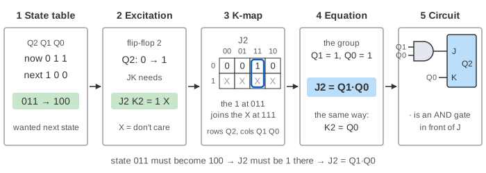
- State table. 6 states need 3 flip-flops, Q2 Q1 Q0. Write the next state beside each present state: 000 → 001 → 010 → 011 → 100 → 101 → 000. States 110 and 111 are unused; their next state is X.
- Excitation table. For each flip-flop and each row, look up the inputs that take Q to Q⁺. In row 011, Q2 goes 0 → 1, so J2 K2 = 1 X.
- K-maps. Each flip-flop input is a function of Q2 Q1 Q0. Copy its column into a Karnaugh map: 6 maps for 3 JK flip-flops.
- Equations. Cover the 1s with the biggest groups. An X counts as 1 when that makes a group bigger. A group may wrap round from the last column to the first; the page draws such a group as two half frames of one colour. The result: J2 = Q1·Q0, K2 = Q0, J1 = Q2'·Q0, K1 = Q0, J0 = K0 = 1.
- Circuit. Each equation is the logic in front of one input. Here that is two AND gates and one inverter; FF0 just has J and K tied to 1.
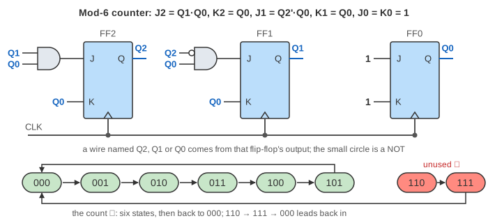
Then the circuit counts. At each edge the gates have already worked out every input from the present state, and each flip-flop holds, sets, resets or toggles on its own (Demo: the mod-6 JK counter counts 0 to 5: 1, 2, 3, 4, 5, 0 in six edges).
What happens in an unused state
The table said X for states 110 and 111. But the circuit is real: once the groups are chosen, every X has become a 0 or a 1, and the counter does something definite in every state. Flip-flops can power up in any state, so this must be checked.
For the mod-6 JK counter, put 110 through the equations: J2 K2 = 0 0 hold, J1 K1 = 0 0 hold, J0 K0 = 1 1 toggle, so 110 → 111. Then 111 → 000. The counter finds its way back in two edges (Demo: unused state 110 finds its way back). The mod-5 T counter has three unused states: 101 → 011, 110 → 010 and 111 → 001, one edge each (Demo: mod-5 with T, three unused states).
A counter that always returns is self-correcting. That is not guaranteed. If the unused states lead only to each other, the counter is stuck in a lock-up; the Johnson counter on Shift Registers and Counters has such a loop. The fix is to replace some X by the value that leads back and redo the map, or to add a reset.
Which flip-flop to use
The same mod-6 counter with each kind of flip-flop (Demo: same counter with D flip-flops):
| flip-flops | input equations | literals | unused states |
|---|---|---|---|
| JK | J2 = Q1·Q0, K2 = Q0, J1 = Q2'·Q0, K1 = Q0, J0 = K0 = 1 | 6 | 110 → 111 → 000 |
| T | T2 = Q2·Q0 + Q1·Q0, T1 = Q2'·Q0, T0 = 1 | 6 | 110 → 111 → 010 |
| D | D2 = Q2·Q0' + Q1·Q0, D1 = Q1·Q0' + Q2'·Q1'·Q0, D0 = Q0' | 10 | 110 → 111 → 100 |
A literal is one variable in a product term, so the count is the number of gate inputs. JK and T flip-flops suit counters because counting is mostly holding and toggling. D flip-flops need more logic here, but they have one input instead of two and their excitation table is trivial (D = Q⁺), so they are what chips and FPGAs use. A larger machine than a counter is designed the same way; see Finite State Machines.
See also Designing a 1011 Sequence Detector, where the same design steps (state table, state assignment, equations, circuit) build a sequence detector with D flip-flops.
What the page leaves out
- Time inside a clock cycle. Gates and flip-flops have no delay here. Real ones do, and the slowest gate path limits the clock rate; see Timing Analysis.
- Asynchronous inputs. Real flip-flops have preset and clear pins that act without the clock. The page sets a power-up state directly.
- Ripple counters, where each flip-flop is clocked by the one before it, and counters with enable, load or up/down inputs.
- Other counts and sizes. The page designs mod-5, mod-6 and mod-7 binary counters on 3 flip-flops. The method is the same for Gray code, BCD or more bits.
- Counters built from SR flip-flops. The SR flip-flop is shown alone; its excitation table is in the text.
- Other minimal covers. When two sets of groups are equally small the page always picks the same one. Another choice can send an unused state somewhere else.
On the mind map
References
Mano and Ciletti, Digital Design, chapter 5 (flip-flops, characteristic and excitation tables, the design procedure) and chapter 6 (counters)