Changing coordinate spaces in 3D
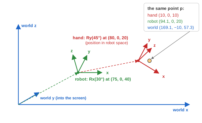
A point's coordinates depend on the frame you measure it in. This page has three frames: world space, robot space (attached to the robot's body) and hand space (attached to its hand). The hand's frame is described relative to the robot, and the robot's relative to the world. With "Show all axes" on, each frame's axes are also drawn inside its parent's picture, so you can see where the hand's x, y and z axes point from the robot's point of view.
A child frame is placed in its parent by an orientation R (a 3×3 rotation matrix) and a position t (the child's origin in parent coordinates). The page shows these as two separate matrices for each frame. The pictures use an oblique projection: x to the right, z up, and y drawn going back into the screen.
The formulas, in the page's convention
With Row Major (the default, used here) points are row vectors multiplied on the left. With Column Major they are column vectors on the right and every matrix is transposed.
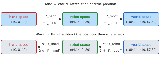
Child -> parent:   p_parent = p_child . R + t            (rotate, then add position)
Parent -> child:   p_child  = (p_parent - t) . R^T       (subtract, then rotate back)

Hand Space -> World Space:              World Space -> Hand Space:
  p_robot = p_hand  . R_hand  + t_hand     p_robot = (p_world - t_robot) . R_robot^T
  p_world = p_robot . R_robot + t_robot    p_hand  = (p_robot - t_hand)  . R_hand^T

Column vectors:  p_parent = R^T . p_child + t,    p_child = R . (p_parent - t)

Axis rotations in the page's row form:
Rx(θ) = [ 1    0      0   ]     Ry(θ) = [ cos θ  0  -sin θ ]
         [ 0  cos θ  sin θ ]              [   0    1    0    ]
         [ 0 -sin θ  cos θ ]              [ sin θ  0   cos θ ]
When you switch to "World Space → Hand Space" the page transposes each orientation matrix, negates each position and moves the position in front of the matrix, because the subtraction has to happen before the rotation.
One 4×4 matrix per frame
Graphics and robotics software usually packs R and t into one 4×4 matrix acting on (x, y, z, 1). Then a chain of frames is a matrix product, read left to right with row vectors:
M = [ R   0 ]     (R is 3x3, the bottom row is t and a 1)
    [ t   1 ]

M_hand->world = M_hand . M_robot
M_world->hand = M_robot^-1 . M_hand^-1        with   M^-1 = [   R^T     0 ]
                                                            [ -t . R^T  1 ]
Worked example with the page's values
In the starting position the robot is tilted by Rx(30°) and stands at (75, 0, 40); the hand is turned by Ry(45°) and sits at (80, 0, 20) in robot space (cos 30° ≈ 0.866, cos 45° = sin 45° ≈ 0.707):
R_robot = [ 1   0      0    ]   t_robot = (75, 0, 40)
          [ 0   0.866  0.5  ]
          [ 0  -0.5    0.866]

R_hand  = [ 0.707  0  -0.707 ]   t_hand = (80, 0, 20)
          [ 0      1   0     ]
          [ 0.707  0   0.707 ]
Enter (10, 0, 10) with "Hand Space → World Space":
Hand -> robot:
  [10 0 10] . R_hand = [ 10·0.707 + 10·0.707,  0,  10·(-0.707) + 10·0.707 ] = [ 14.142  0  0 ]
  + t_hand           = [ 94.142  0  20 ]

Robot -> world:
  [94.142 0 20] . R_robot = [ 94.142,  0·0.866 + 20·(-0.5),  0·0.5 + 20·0.866 ] = [ 94.142  -10  17.321 ]
  + t_robot               = [ 169.142  -10  57.321 ]
(The 14.142 is exactly 10√2: the hand point lies on the hand's 45° diagonal, and the rotation lines it up with the robot's x axis.) Now switch to "World Space → Hand Space" and enter (169.142, −10, 57.321):
World -> robot:
  [169.142 -10 57.321] - t_robot = [ 94.142  -10  17.321 ]
  . R_robot^T   (R_robot^T = [ 1 0 0 ; 0 0.866 -0.5 ; 0 0.5 0.866 ])
      = [ 94.142,  -10·0.866 + 17.321·0.5,  -10·(-0.5) + 17.321·0.866 ] = [ 94.142  0  20 ]

Robot -> hand:
  [94.142 0 20] - t_hand = [ 14.142  0  0 ]
  . R_hand^T    (R_hand^T = [ 0.707 0 0.707 ; 0 1 0 ; -0.707 0 0.707 ])
      = [ 14.142·0.707,  0,  14.142·0.707 ] = [ 10  0  10 ]
The round trip returns the original point. (This page keeps full precision internally and only displays two decimals, so it lands on (10, 0, 10) exactly.) As a single 4×4 matrix:
M_hand->world = M_hand . M_robot = [ 0.707   0.354  -0.612  0 ]
                                   [ 0       0.866   0.5    0 ]
                                   [ 0.707  -0.354   0.612  0 ]
                                   [ 155    -10     57.321  1 ]

[10 0 10 1] . M = [ 7.07 + 7.07 + 155,  3.54 - 3.54 - 10,  -6.12 + 6.12 + 57.321,  1 ]
                = [ 169.142  -10  57.321  1 ]
The top three rows are the hand's x, y and z axes in world coordinates, and the bottom row (155, −10, 57.321) is where the hand's origin is in the world: (80, 0, 20) · Rrobot + (75, 0, 40).
Why it works
The rows of Rhand are the hand's three axes written in robot coordinates. So p · R + t = t + x·(hand x axis) + y·(hand y axis) + z·(hand z axis): start at the hand's origin and step along its axes. Going back, the offset p − t has to be split into amounts along each axis. The axes are perpendicular unit vectors, so each amount is a dot product, and the three dot products together are multiplication by RT. In other words R · RT = I and the inverse of a rotation is its transpose. Changing from parent to child coordinates always means applying the inverse of the transform that places the child, with the steps in reverse order.
Cost and practical notes
Each frame step is 9 multiplications and 3 additions. For many points, multiply the frame matrices once and apply the single 4×4 result to each point (16 multiplications, or 12 when the last column is known to be 0, 0, 0, 1). A rigid transform's inverse needs only a transpose and one vector product, never a general 4×4 inversion. Scene graphs cache each node's local-to-world matrix; when the robot moves, only its matrix changes and everything attached to it follows. The camera works the same way: the view matrix is the inverse of the matrix that places the camera in the world, and a GPU multiplies model, view and projection matrices into one before drawing.
Common mistakes
- Order of the chain. Hand → world applies the hand step first; world → hand undoes the robot step first.
- Subtract, then rotate. The inverse is (p − t) · RT, not p · RT − t.
- Which frame t is in. thand is measured in robot space; adding it to a world-space point is wrong.
- Row vs column convention. With column vectors the translation is the last column and the orientation matrix is transposed; mixing conventions turns rotations backwards.
- Transpose is only the inverse for pure rotations. If a frame is scaled, use the real inverse (and the inverse transpose for normals).
- Handedness and sign conventions. Libraries differ on right- vs left-handed axes and on the sign in Ry; check before copying matrices.
- Degrees vs radians in code, and rounding: rounded matrices are not exactly orthogonal, so round trips drift slightly.
Where it is used
Robot arms chain one frame per joint to find the gripper (forward kinematics), and ROS's tf library maintains such a frame tree. Games and animation attach weapons to hand bones and cameras to vehicles; skeletal animation chains bone matrices; AR and VR convert between head, controller and room frames; aircraft convert between body and ground frames; and every 3D renderer converts model → world → camera space for each vertex. CSS 3D transforms on nested elements compose the same way.