The idea: every pod has an IP, a Service is only a rule
In Kubernetes every pod gets its own IP address, and any pod can reach any other pod at that address without NAT. But pods
come and go, so clients do not call pods. They call a Service: a stable virtual IP (the ClusterIP,
here 10.96.0.50:80) with a name in DNS (api). No network card has the ClusterIP. It exists only as a
rule in the kernel of every node, and the rule rewrites the destination to a real pod.
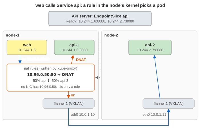
The page follows one HTTP request, GET /orders, from the web pod to the api Service.
The canvas shows the control plane at the top: the API server's Services and the EndpointSlice,
which lists the Ready pods behind Service api. Below it are two nodes. Each node has pods at the top, each in
its own network namespace. Under them is the node's own (host) network namespace: the bridge cni0, the
nat rules that kube-proxy wrote, the conntrack table, the routes and the VXLAN device
flannel.1. At the bottom is the node network that connects the nodes' eth0, an outside client and the internet.
Every connection has one colour, used by its packets, its sockets and its conntrack rows. The line under the canvas shows the
packet's header.
To keep the canvas readable it only shows what the current packet touches: the nat rules it walks (the whole table is
listed below), the conntrack rows of the node it is on, and each pod's newest socket. Colours:
orange = rewritten by NAT (and the rule that picked the pod),
blue = rule or conntrack row in use,
red = dropped or rejected. A conntrack row shows the original tuple, its state, and
what conntrack rewrites on it: DNAT to the pod, SNAT to the node.
Inside a pod: network namespace and veth pair
A pod is a group of containers that share one network namespace: one eth0, one IP, one routing table,
one set of ports. That eth0 is one end of a veth pair, a virtual cable. The other end lives in the
node's host namespace and is plugged into the bridge cni0. The CNI plugin (here a flannel-like one)
builds all this when the pod starts and gives it an IP from the node's pod CIDR (10.244.1.0/24 on node-1). So every packet
a pod sends lands in the host's kernel, and that is where Kubernetes networking happens.
ClusterIP = iptables DNAT
kube-proxy runs on every node. It watches Services and EndpointSlices and writes chains into the
nat table. The first packet of a connection (the SYN) walks them:
| Chain | Rule | Effect |
|---|---|---|
PREROUTING | -j KUBE-SERVICES | every packet entering the node |
KUBE-SERVICES | -d 10.96.0.50/32 -p tcp --dport 80 -j KUBE-SVC-… | one rule per Service port |
KUBE-SVC-… | -m statistic --mode random --probability 0.5 -j KUBE-SEP-1, then -j KUBE-SEP-2 | load balancing: with n endpoints the rules use 1/n, 1/(n−1), …, 1 |
KUBE-SEP-… | -j DNAT --to-destination 10.244.2.7:8080 | the destination becomes a pod |
The whole nat table kube-proxy writes on node-1 in the page's cluster (the canvas only shows the rows a packet walks):
PREROUTING      every packet (from pods and from eth0) → KUBE-SERVICES
KUBE-SERVICES   -d 10.96.0.50 tcp dpt:80 → KUBE-SVC-API
                -d 10.96.0.10 udp dpt:53 → KUBE-SVC-DNS
                dst-type LOCAL (this node's IP) → KUBE-NODEPORTS
KUBE-NODEPORTS  tcp dpt:30080 → KUBE-MARK-MASQ, KUBE-SVC-API      (Local: → KUBE-SVL-API)
                tcp dpt:30081 → KUBE-SVL-ING
KUBE-SVC-API    random 0.50 → SEP-API1: DNAT 10.244.1.6:8080
                → SEP-API2: DNAT 10.244.2.7:8080
KUBE-SVL-API    → the api pod on this node, or DROP                (only with Local)
KUBE-SVC-DNS    → SEP-DNS: DNAT 10.244.2.3:53
KUBE-SVL-ING    → SEP-ING: DNAT 10.244.1.8:80                      (node-2: DROP, no ingress pod)
POSTROUTING     mark 0x4000 → MASQUERADE (src = outgoing interface)
                -s 10.244.0.0/16 ! -d 10.244.0.0/16 → MASQUERADE
So "load balancing" is a random number drawn once per connection, inside the kernel of the client's node. No proxy process touches the packets. The name kube-proxy comes from its first version, which really was a user-space proxy. The page draws the random number from a seeded generator, so the demos always pick the same pods. The backend select can force a pick.
Only the first packet: conntrack and the reverse NAT
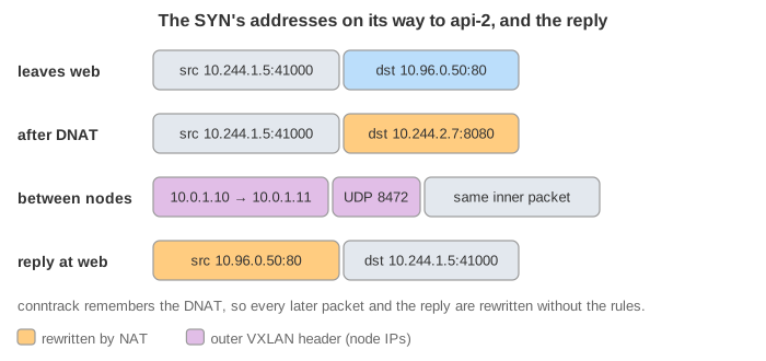
After the DNAT, conntrack stores the flow twice: the original tuple
(10.244.1.5:41000 → 10.96.0.50:80) and the tuple it expects for replies (10.244.2.7:8080 → 10.244.1.5:41000).
Every later packet (the ACK, the request, the FIN) matches the row and is rewritten the same way, without walking the rules. When the
reply arrives, conntrack rewrites its source back to 10.96.0.50:80. That matters: the client's socket is
connected to 10.96.0.50:80 and would drop a segment from any other address.
One consequence surprises people. Because the backend is chosen per connection, a client with HTTP keep-alive sends every request to the same pod. A gRPC or HTTP/2 client that keeps one connection open never spreads its load (Demo 3: Keep-alive pins one backend). If you need per-request balancing, use a client-side balancer or a service mesh.
Crossing nodes: routes and VXLAN
After the DNAT the destination is a pod IP. If that pod is on the same node, the route 10.244.1.0/24 dev cni0 sends it
straight to the bridge (Demo 2). If it is on node-2, the route 10.244.2.0/24 via flannel.1 hands it to the
VXLAN device. That device wraps the whole packet in an outer UDP packet from 10.0.1.10 to
10.0.1.11, port 8472, and node-2 unwraps it. The physical network only ever sees node IPs. The 50 extra bytes are why
pod interfaces get an MTU of 1450. There is no NAT between pods: api-2 sees the web pod's real IP.
| CNI style | How a packet reaches another node | Examples |
|---|---|---|
| Overlay (VXLAN, Geneve) | encapsulate in UDP between node IPs; works on any network | flannel (vxlan), Calico VXLAN mode, Cilium tunnel mode |
| Routed | plain IP routes to each node's pod CIDR, learned via BGP or the cloud's route table; no extra header | Calico BGP, flannel host-gw, Cilium native routing |
| Cloud VPC | pods get real VPC addresses from the cloud network | AWS VPC CNI, Azure CNI, GKE VPC-native |
Finding the Service: CoreDNS
The app asks for http://api/orders. The pod's /etc/resolv.conf points at the kube-dns Service
(10.96.0.10). Its search list (default.svc.cluster.local svc.cluster.local cluster.local) with
ndots:5 turns api into api.default.svc.cluster.local. The query is UDP to a Service IP, so it
is DNATed to a CoreDNS pod like any other traffic. The answer is the ClusterIP, not a pod IP (Demo 1). A
headless Service (clusterIP: None) would return the pod IPs instead.
From outside: NodePort, SNAT and externalTrafficPolicy
A NodePort Service opens the same port (here 30080) on every node. A client sends to
node-ip:30080, and KUBE-NODEPORTS DNATs the packet to some pod, maybe on another node. That creates a problem.
If node-2 forwards the packet to api-1 on node-1 unchanged, api-1 answers the client directly from 10.244.1.6. The
client expected the reply from 10.0.1.11:30080 and drops it. So with externalTrafficPolicy: Cluster (the default)
kube-proxy marks the packet and masquerades it: the source becomes node-2's address on the outgoing interface. With
flannel that is flannel.1's 10.244.2.0. The reply goes back to node-2, which undoes both rewrites. The price:
the pod never sees the client's IP (Demo 4).
externalTrafficPolicy: Local only uses pods on the node that received the packet. Then no SNAT is needed: the reply
leaves from the same node anyway, and the pod sees the real client address. The price: a node with no such pod drops the traffic.
A cloud load balancer avoids that node by probing healthCheckNodePort (Demo 5). A
LoadBalancer Service is a NodePort Service plus that cloud load balancer in front of the nodes.
Ingress: an HTTP proxy that runs in a pod
An Ingress is a set of HTTP routing rules (host and path → Service). The page has one:
host shop.example.com, path /orders → service api:80. An ingress controller,
here ingress-nginx, reads those rules and configures nginx. It is reached through its own NodePort or LoadBalancer Service. It
usually has externalTrafficPolicy: Local, so nginx sees the client IP and can pass it on in
X-Forwarded-For. Unlike kube-proxy it works at layer 7. It terminates the client's TCP (and TLS)
connection, reads the Host header and path, and opens a second connection to a backend. ingress-nginx
watches EndpointSlices itself and connects straight to pod IPs, so kube-proxy's DNAT is not used on that hop. Because it balances
per request, keep-alive does not pin clients to one pod (Demo 6).
EndpointSlices, readiness and stale connections
Only pods whose readiness probe passes are listed in the EndpointSlice. When a pod dies or turns unready, the
endpoint controller removes it and every kube-proxy rewrites its chains. New connections stop going there. But conntrack rows of
connections that are already open still point at the old pod IP. kube-proxy flushes stale UDP rows, not TCP ones. So a client that
reuses a keep-alive connection sends its next request into a black hole and only notices at its timeout (Demo 7). Graceful
shutdown avoids this: preStop delays and connection draining let the pod close its connections cleanly. A Service with no
endpoints at all gets a REJECT rule, so clients fail fast with connection refused (Demo 8).
Egress: pods calling the internet
Pod IPs mean nothing outside the cluster. When a pod connects to an outside address, the node masquerades the packet: its source becomes the node's IP, and conntrack undoes the rewrite on the replies, exactly like a home router (see How NAT Shares One Public Address). The rule is "source in the pod CIDR and destination outside it → MASQUERADE" (Demo 8). Clusters that need a fixed source address use an egress gateway or a cloud NAT in front of the nodes.
kube-proxy modes and alternatives
| Mode | How a Service is implemented | Notes |
|---|---|---|
| iptables (shown here) | nat chains, random probability rules, conntrack | rule lookup is a linear list; with tens of thousands of Services, updates and first-packet cost grow |
| IPVS | an in-kernel L4 load balancer with a hash table of virtual servers | round robin, least-connection and others; scales to many Services; deprecated in favour of nftables |
| nftables | the same ideas with nftables maps (verdict maps instead of long chains) | GA in Kubernetes 1.33; faster updates and lookups |
| eBPF (Cilium, kube-proxy replacement) | BPF programs translate at the socket (connect()) or at the interface | no per-packet NAT for pod-to-Service traffic; can keep the client IP |
See also The Life of a Kubernetes Pod (how a pod gets scheduled, started, probed and terminated before and after it is in the EndpointSlice), How NAT Shares One Public Address (SNAT, DNAT and conntrack on a home router), How an HTTP Connection Is Established (the TCP handshake and close in detail), How a DNS Name Is Resolved and Internet Protocol Layers.
What the page leaves out
NetworkPolicy (firewall rules, also enforced by the CNI), IPv6 and dual-stack, service meshes and sidecars, session affinity,
topology-aware routing, hairpin traffic (a pod reaching itself through its own Service is masqueraded too), the
KUBE-MARK-MASQ rule for ClusterIP traffic from outside the pod network, ARP and MAC addresses on the bridge, TLS,
conntrack timeouts and real random ports. The page compresses the TCP close into FIN and FIN-ACK, with the last ACK only told in text.