The idea: let the device tell the CPU when it is done
A device is millions of times slower than the CPU. If the CPU waited for every byte, it would spend almost all its time waiting. With interrupt-driven I/O, the CPU starts the device and then runs other work. When the device is done, it sends the CPU a signal: an interrupt. The CPU stops what it is doing, runs a short interrupt handler for that device, and then goes back to exactly where it was.
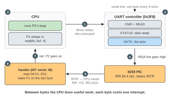
The textbook draws this as a cycle of seven steps. The animation numbers its titles the same way:
- The driver starts the I/O: it writes a command into the device controller's registers.
- The controller does the I/O by itself. The process that asked sleeps, and another one runs.
- The CPU runs other work and checks for interrupts after every instruction.
- The device finishes and raises its interrupt line.
- The CPU takes the interrupt: it saves where it was and jumps to the handler.
- The handler processes the data, then returns from the interrupt.
- The CPU resumes the interrupted task.
In the animation, P1 calls read(fd, buf, 4) on a serial port while P2 is a CPU-bound loop. One tick is one instruction. The device needs 6 ticks to deliver each byte. (Demo: the I/O cycle.)
Device controllers and their registers
The CPU never touches the wire or the disk platter. It talks to a device controller, a small chip with a few registers. On a PC, the serial port (a UART) sits at I/O port 0x3F8:
| Register | Who writes it | What it means |
|---|---|---|
| command (CMD) | the driver | what to do: here, READ, and whether to interrupt when done |
| status (STATUS) | the controller | busy, or data ready (a real UART calls this bit DR in its line status register) |
| data (DATA) | the controller, on input | the byte that arrived; reading it acknowledges the controller |
The CPU reaches these registers with special in / out instructions (port-mapped I/O), or with ordinary loads and stores to reserved addresses (memory-mapped I/O, what most modern devices use). Either way, each access is a trip over the bus. In the animation it is the yellow box that flies from the CPU to the controller.
See also Embedded I/O: the hardware below this cycle — the address decoder that routes a sw to a device register, a UART frame bit by bit, and a timer interrupt compared with polling.
The instruction cycle and the interrupt check
The CPU repeats fetch → decode → execute. After each instruction it looks at its INTR pin. If the pin is low, it fetches the next instruction. If the pin is high and the IF flag in RFLAGS is 1, it takes the interrupt instead. So an interrupt never lands in the middle of an instruction. The ring at the top of the CPU panel lights INTR? when that happens.
cli clears IF and sti sets it. While IF is 0 the CPU ignores INTR. The kernel does this for short stretches, for example in spin_lock_irqsave(), when an interrupt handler could touch the same data. (A non-maskable interrupt, NMI, ignores IF. It is used for hardware errors and watchdogs.)
Taking an interrupt: PIC, vector, IDT, frame, iret
Devices do not wire straight into the CPU. Each device has an IRQ line into an interrupt controller. The page uses the classic 8259 PIC with three lines: IRQ0 timer, IRQ4 serial, IRQ14 disk. When a line goes high, the PIC sets that IRQ's bit in its IRR (interrupt request register) and raises INTR. When the CPU takes the interrupt:
- It sends INTA (interrupt acknowledge). The PIC answers with a vector number (IRQ n → vector 32 + n, so IRQ4 is 36) and moves the bit from IRR to ISR (in service).
- It pushes the interrupt frame onto the current task's kernel stack: RIP (where to come back to), CS (which says user or kernel mode) and RFLAGS (with IF). Coming from user mode, it first switches to the task's kernel stack. It also pushes SS and RSP, which the page leaves out.
- It clears IF and jumps to the handler that the IDT (interrupt descriptor table) lists for that vector. Vectors 0–31 are the CPU's own exceptions, such as 14, the page fault.
- The handler ends with
iret, which pops RIP, CS and RFLAGS. IF is 1 again, and the interrupted code goes on. It cannot tell that anything happened, except that time passed.
What the handler does
A handler runs with interrupts off and has interrupted somebody else. So it does as little as it can. It reads the data or status, which acknowledges the device so its line drops. It starts the next transfer if there is one. It sends EOI (end of interrupt), which clears the ISR bit so the PIC can deliver more interrupts. On the last byte it wakes the waiting process. Waking only moves P1 to the run queue and sets need_resched. The actual switch to P1 happens when the kernel is about to return to P2's user code.
Linux splits handlers in two. The top half is the real handler, short, with interrupts off. The bottom half (softirq, tasklet, workqueue or threaded IRQ) runs later with interrupts on, for the slow work. A network card's handler, for example, only schedules the receive softirq. The animation's handler is all top half.
Polling vs interrupts vs DMA
Run the three demos for the same 4-byte read (Demo: compare all three runs them back to back, and the lines under the timeline keep the results):
| Polling | Interrupt-driven | DMA | |
|---|---|---|---|
| CPU while the device works | spins on STATUS | free: runs P2 | free: runs P2 |
| CPU work per byte | a whole poll loop | one interrupt: entry, handler, iret | none (one bus cycle is stolen) |
| Interrupts for n bytes | 0 | n | 1 |
| 4 bytes at 6 ticks/byte (this page) | 35 ticks, P2 gets 0, 24 polls | 38 ticks, P2 gets 16 (42%), 4 interrupts | 32 ticks, P2 gets 22 (69%), 1 interrupt |
| Wins when | the device answers within a few cycles, or the CPU has nothing else to do | slow devices with little data: keyboard, mouse, serial | bulk data: disks, network cards, GPUs |
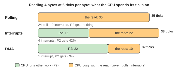
Polling has the lowest latency: the driver sees the byte one tick after it is ready, with no entry or exit cost. That is why very fast devices (NVMe with io_uring polling, DPDK network drivers) poll on purpose and dedicate a core to it.
With DMA (direct memory access), the driver gives the controller a memory address and a byte count. The controller becomes a bus master and writes each byte into memory itself. Each write takes the bus for a cycle (cycle stealing), drawn in purple above the timeline. The CPU hears from the controller once, when COUNT reaches 0. Real controllers take a list of buffers (a scatter-gather list), not one address.
Masking, pending and priority
An interrupt that cannot be delivered yet is pending, not lost. Its bit waits in IRR until two things are true: IF is 1, and no interrupt of the same or higher priority is in service. The delay is interrupt latency. This is why kernels keep cli sections short. (Demo: masked (cli): the byte is ready while P2 is in a spin_lock_irqsave() section. IRQ4 waits 3 extra ticks and is taken right after sti.)
When two lines are raised in the same tick, the PIC hands over the highest-priority one first. On the 8259, a lower IRQ number means higher priority. (Demo: timer + serial IRQ: IRQ0 is taken first. IRQ4 stays in IRR through the timer handler, its EOI and its iret, 4 ticks in all, and is taken on the very next instruction.)
When interrupts eat the CPU
Every interrupt costs a fixed number of instructions, here 4 ticks: entry, two handler instructions and iret. On real hardware it costs more, because caches and pipelines are disturbed too. If the device delivers a byte every 2 ticks, almost every tick goes to interrupt code. Demo: fast device reads 8 bytes both ways. With interrupts the read takes 38 ticks, 84% of them in interrupt code, and P2 gets none. With DMA it takes 24 ticks with one interrupt, and P2 gets 14.
A network card at full speed can go further: it keeps the CPU so busy taking interrupts that the packets are never processed. This is receive livelock. Fixes: interrupt coalescing (one interrupt per many packets or per time period), and Linux NAPI, which turns the device's interrupt off under load and polls instead. That combines the strengths of polling and interrupts.
How to see it on Linux
cat /proc/interrupts: one line per IRQ, a counter per CPU, the controller type (IO-APIC, PCI-MSI) and the driver name.vmstat 1: theincolumn is interrupts per second,cscontext switches per second.cat /proc/softirqsfor bottom halves./proc/irq/<n>/smp_affinityandirqbalancechoose which CPUs take an IRQ.perf stat -e irq:irq_handler_entryorbpftraceonirq:irq_handler_entryto count handlers.
See also Kinds of Interrupts in Linux (device IRQ, timer, NMI, page fault and system call side by side on a modern APIC machine), Linux Context Switch (what schedule() does when P1 sleeps and wakes), epoll (one thread waiting on many devices), Linux Virtual Memory (the page fault, vector 14 in the same IDT) and MIPS Pipeline.
What the page leaves out
One CPU. Modern PCs use the APIC (a local APIC per core plus an I/O APIC) and MSI/MSI-X, where a PCIe device sends its interrupt as a memory write and gets its own vector, so there is no shared line and no 8259. IRQ affinity across cores. The IOMMU that checks DMA addresses. A real UART's FIFO, which batches 14 bytes per interrupt. Exceptions and page faults, which use the same IDT. Interrupts while already in a handler (Linux handlers run with IF = 0, so they do not nest). The extra pushes (SS, RSP, error codes). And the real costs: an interrupt is hundreds to thousands of cycles, not 4.