What the animation shows
The MIPS datapath page runs one instruction at a time: an instruction goes through its five stages, and only then does the next one start. This page runs the same instructions, the same programs and nearly the same drawing, but pipelined, as in Hennessy and Patterson's Computer Architecture: A Quantitative Approach, Appendix C. In every clock cycle each of the five stages works on a different instruction, so up to five instructions are in flight at once.
Press Step Cycle. Each instruction has its own colour: the stage titles at the top say which instruction each stage works on, the wires a stage uses light up in that instruction's colour, and yellow chips carry the values into the pipeline registers, whose fields turn green when they are written. Under the datapath, the pipeline diagram grows one column per cycle, so you see the same moment twice: where each instruction is in the hardware, and when it got there.
From one instruction at a time to a pipeline
Think of a laundry with a washer, a dryer and an ironing board. Doing one load completely before starting the next wastes the washer while the dryer runs. Starting the next wash as soon as the washer is free does not make any single load faster, but a load comes out every "stage time" instead of every "whole-job time".
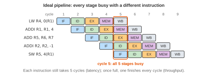
The pipeline works the same way. Each instruction still takes 5 cycles from fetch to write back (its latency), but once the pipeline is full, one instruction finishes every cycle (the throughput). With no hazards, N instructions take N + 4 cycles: 4 cycles to fill the pipeline, then one per instruction. The CPI tends to 1.
The pipeline registers
The temporary registers of the multicycle datapath (NPC, IR, A, B, Imm, ALUOutput, Cond, LMD) become four pipeline registers, the tall grey columns, named after the two stages they sit between. At the end of every cycle all four are written at once. Each one holds everything the rest of the instruction needs, because the stage before it is already working on the next instruction:
| Register | Fields | Why |
|---|---|---|
IF/ID | IR, NPC | the fetched instruction and PC + 4 |
ID/EX | IR, NPC, A, B, Imm | the operands read in ID; NPC for a branch target |
EX/MEM | IR, ALUOutput, B, Cond | the ALU result or address; B is the data a store writes |
MEM/WB | IR, ALUOutput, LMD | the value to write back |
Note that IR travels with the instruction. In the multicycle datapath there was one IR, and WB could read the destination register number from it. Here, by the time an instruction reaches WB, IF/ID holds an instruction three places younger. So each pipeline register carries its own copy, and the register number written in WB comes from MEM/WB.IR (the wire along the bottom into wr#).
What each stage does
| Stage | Register transfers |
|---|---|
| IF | IF/ID.IR ← Mem[PC]; IF/ID.NPC, PC ← (EX/MEM holds a taken branch) ? EX/MEM.ALUOutput : PC + 4 |
| ID | ID/EX.A ← Regs[rs]; ID/EX.B ← Regs[rt]; ID/EX.Imm ← sign-extend(imm16); ID/EX.IR ← IF/ID.IR; ID/EX.NPC ← IF/ID.NPC |
| EX | EX/MEM.IR ← ID/EX.IR; ALU: ALUOutput ← A' op B' or A' op Imm; load/store: ALUOutput ← A' + Imm, EX/MEM.B ← B'; branch: ALUOutput ← NPC + (Imm << 2), Cond ← (A' == 0) (≠ for BNEZ) |
| MEM | MEM/WB.IR ← EX/MEM.IR; ALU: MEM/WB.ALUOutput ← EX/MEM.ALUOutput; load: MEM/WB.LMD ← Mem[EX/MEM.ALUOutput]; store: Mem[EX/MEM.ALUOutput] ← EX/MEM.B |
| WB | ALU: Regs[rd or rt] ← MEM/WB.ALUOutput; load: Regs[rt] ← MEM/WB.LMD |
A' and B' are A and B after the two forwarding muxes in front of the ALU (see below). The PC mux has moved into IF: it picks PC + 4, or the branch target when the branch in MEM is taken.
Reading the pipeline diagram
One row per fetched instruction, one column per clock cycle; a cell says which stage the instruction is in during that cycle. An ideal pipeline is a staircase: each row starts one cycle after the one above. The current cycle's column is yellow. ID* and IF* (orange) are stalled cycles; a grey (bubble) row is the empty slot a stall sends down the pipe; rows struck out with a red ✗ were flushed (thrown away) in the cell marked ✗. An arrow from one row to another is a forward: the value goes from the producer's pipeline register straight into the consumer's ALU. Light grey nop rows are the zero words fetched past the end of the program.
Data hazards
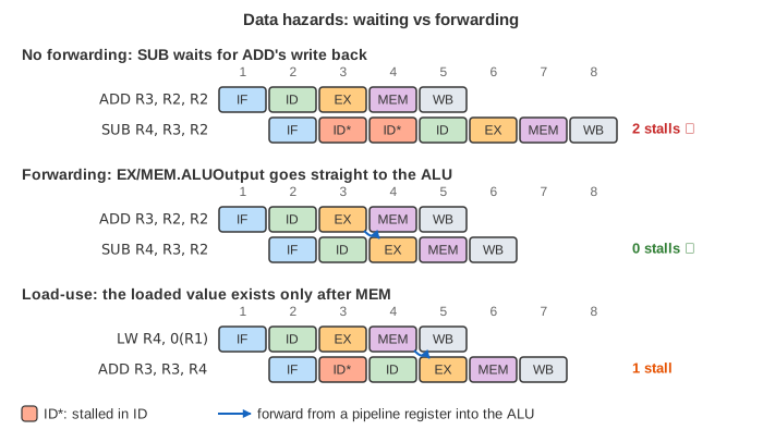
In ADD R3, R2, R2 followed by SUB R4, R3, R2, SUB reads R3 in ID one cycle after ADD computed it in EX, but ADD writes R3 only in WB, two cycles later still. Reading the register file would give the old value: a read-after-write (RAW) hazard. The other two kinds cannot happen in this pipeline: every instruction reads its registers in ID and writes in WB, in program order, so a later instruction can never write a register before an earlier one reads it (WAR) or before an earlier one writes it (WAW).
Without forwarding (untick Forwarding), the only cure is to wait. The hazard detection unit in ID compares the source registers of the instruction in ID with the destinations of the instructions in EX and MEM; on a match it stalls: PC and IF/ID keep their values (the red "hold" tags), and a bubble (an empty slot, a nop) goes into ID/EX instead of the instruction. It waits until the producer reaches WB, because the register file is written in the first half of the cycle and read in the second half: an instruction in ID reads the value WB writes in the same cycle. So a consumer right after its producer (distance 1) stalls 2 cycles, at distance 2 it stalls 1 cycle, and from distance 3 on nothing is lost.
Forwarding
The value SUB needs exists at the end of ADD's EX: it sits in EX/MEM.ALUOutput one cycle later, just when SUB is in EX. Forwarding (also called bypassing) sends it there directly. Two forwarding muxes in front of the ALU inputs choose between the register value read in ID, EX/MEM.ALUOutput (the instruction one ahead) and the value about to be written back from MEM/WB (two ahead). When both hold the register, the newer one, EX/MEM, wins. In P&H's notation the conditions for the first ALU input are:
if (EX/MEM.RegWrite and EX/MEM.RegisterRd ≠ 0 and EX/MEM.RegisterRd = ID/EX.RegisterRs)  ForwardA = EX/MEM
else if (MEM/WB.RegWrite and MEM/WB.RegisterRd ≠ 0 and MEM/WB.RegisterRd = ID/EX.RegisterRs)  ForwardA = MEM/WB
else ForwardA = register file (ID/EX.A)
and the same with Rt and B for the second. The forwarded value also feeds Zero? (a branch tests it) and EX/MEM.B (a store writes it). In the animation the forward wire lights up in the colour of the producer, so you see the value come from the older instruction.
Load-use: the one stall forwarding cannot remove
A load reads memory in MEM, so its value exists only at the end of MEM. The instruction right after it is in EX in that same cycle: too early. The hazard detection unit therefore still stalls one cycle when the instruction in ID reads the destination of a load in EX; after the bubble, the value is forwarded from MEM/WB.LMD. The Hazard sampler program shows every case once: EX/MEM forwarding, the load-use bubble, MEM/WB forwarding, forwarding the data of a store, and a read from the register file in the cycle it is written.
A compiler avoids the bubble by scheduling an independent instruction between the load and its use. Try it on the Custom tab: lw r2, 0x100(r0) | add r3, r2, r2 | lw r4, 0x104(r0) | add r5, r4, r4 takes 10 cycles with 2 stalls; lw r2, 0x100(r0) | lw r4, 0x104(r0) | add r3, r2, r2 | add r5, r4, r4 does the same work in 8 cycles without a stall.
Control hazards: branches
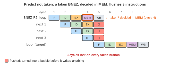
In this pipeline, as in the H&P figure, a branch is decided in MEM (EX/MEM.Cond). By then three younger instructions are already in IF, ID and EX. Two ways to handle them (the Branch select):
- Freeze: as soon as ID sees a branch, stop fetching until MEM has decided. The instruction fetched while the branch was in ID is thrown away. 3 cycles are lost on every branch, taken or not.
- Predict not taken: keep fetching the next instructions in order. If the branch is not taken they are the right ones and nothing is lost. If it is taken, the three are flushed: turned into bubbles before they write a register or memory, and IF fetches from the target in the next cycle. 3 cycles are lost on a taken branch only.
Real pipelines do better: MIPS moves the test into ID (a comparator next to the register file, and a separate adder for the target), which costs only 1 cycle, and fills that cycle with a branch delay slot: the instruction after a branch is always executed. Modern processors predict the outcome of every branch from its history (dynamic branch prediction) and fetch from the predicted target.
See also Branch Prediction on the MIPS Pipeline: a branch target buffer, 1-bit and 2-bit counters and gshare predict each branch in fetch, and wrong guesses are flushed and counted in the CPI.
Beyond one instruction per cycle: Superscalar and Out-of-Order Execution runs a program on a 2-wide in-order machine, an out-of-order scoreboard and an out-of-order machine with register renaming and a reorder buffer, and squashes a mispredicted branch.
Counting cycles
Every cycle lost is a slot that goes through WB with no instruction in it, so
cycles = N + 4 (fill) + stall cycles + flushed (or frozen) cycles CPI = cycles / N
The array sum runs 19 instructions: three set-up, three loop turns of LW, ADD, ADDI, ADDI, BNEZ, and the final SW. With forwarding, each turn has one load-use stall (ADD R3, R3, R4 right after LW R4); two of the three BNEZ are taken:
| Array sum | predict not taken (flush) | freeze |
|---|---|---|
| forwarding | 32 = 19 + 4 + 3 + 6, CPI 1.68 | 35 = 19 + 4 + 3 + 9, CPI 1.84 |
| no forwarding | 41 = 19 + 4 + 12 + 6, CPI 2.16 | 44 = 19 + 4 + 12 + 9, CPI 2.32 |
Without forwarding the loop loses 4 stall cycles per turn instead of 1 (ADD waits 2 for LW, BNEZ waits 2 for ADDI R2). Freeze adds 3 cycles for the last, not-taken BNEZ, which predict-not-taken gets for free.
Pipelined, single-cycle, multicycle
Tick Compare with single-cycle. With P&H's stage times (IF 200 ps, ID 100, EX 200, MEM 200, WB 100), a single-cycle CPU needs an 800 ps clock (a load uses all five stages in one cycle) but has CPI 1; the multicycle datapath and the pipeline both run a 200 ps clock (the slowest stage).
| Program | pipelined | single-cycle | multicycle |
|---|---|---|---|
| Array sum | 32 × 200 ps = 6.4 ns | 19 × 800 ps = 15.2 ns | 91 × 200 ps = 18.2 ns |
| Hazard sampler | 11 × 200 ps = 2.2 ns | 6 × 800 ps = 4.8 ns | 29 × 200 ps = 5.8 ns |
| One of each | 17 × 200 ps = 3.4 ns | 9 × 800 ps = 7.2 ns | 42 × 200 ps = 8.4 ns |
| Max of two | 15 × 200 ps = 3.0 ns | 7 × 800 ps = 5.6 ns | 32 × 200 ps = 6.4 ns |
The pipeline wins, but by 2.4× on the array sum, not by 4× or 5×: the stages are not balanced (ID and WB need only 100 ps), and the 4 fill cycles, the stalls and the flushes all count. Real pipelines also pay for the pipeline registers themselves (some tens of picoseconds per stage), which this model leaves out.
Try it
- The tabs above the controls load a program at once. Hazard sampler, cycle by cycle: watch the forward wires in EX and the arrows in the diagram. Then untick Forwarding and count the stalls (8 instead of 1).
- Array sum with Branch: freeze and then predict not taken: the last loop turn is where they differ.
- The Custom tab's field takes instructions separated by
|, with labels if you like (addi r1, r0, 3 | loop: addi r1, r1, -1 | bnez r1, loop), up to 12 of them. Data memory starts as 5, 7, 9 at 0x100, 0x104, 0x108. add r1, r0, r0 | add r2, r1, r1 | add r3, r1, r1 | add r4, r1, r1reads R1 at distance 1, 2 and 3: without forwarding the stalls are 2, 0, 0 (the first stall also lets the other two through).
What the animation leaves out
- The branch is decided in MEM, as in the H&P figure, with a 3-cycle penalty. Real MIPS decides it in ID and has a branch delay slot; neither is modelled.
- Programs end by running into zero words:
0x00000000is the real MIPSnop(sll r0, r0, 0). The run stops when the last real instruction leaves WB. - No pipeline-register delay in the clock, no caches: every memory access takes one cycle. The stage times are P&H's textbook numbers, not a real chip.
- A store's data register is checked by the load-use rule like any other source, as in P&H's hazard unit, although a load followed by a store of the loaded value could be forwarded in MEM without a stall.
- No exceptions, no multi-cycle floating-point units, no structural hazards (instruction and data memories are separate, as in the figure). Only 8 registers, 12 words of instruction memory and 8 words of data memory.
- The logic inside each stage (the ALU, the muxes, the forwarding comparators) is drawn as boxes; how it is built from gates, and why its delay sets the stage time, is on Combinational Logic.
References
Classic RISC pipeline (Wikipedia)
Hennessy and Patterson, Computer Architecture: A Quantitative Approach, Appendix C: Pipelining, Basic and Intermediate Concepts
Patterson and Hennessy, Computer Organization and Design, chapter 4: The Processor (pipelining, data hazards and forwarding, control hazards)