The idea: the carry is the bottleneck
A ripple-carry adder chains N full adders: bit i cannot finish until the carry from bit i − 1 has arrived. Its delay grows with the width, tripple = N·tFA. With a 300 ps full adder a 32-bit add takes 9.6 ns, far too slow for a processor that runs at 1 GHz. The Combinational Logic page builds that 4-bit adder gate by gate; this page is about the circuits that remove the chain.
The canvas uses static timing, as the textbook does: every block has a fixed worst-case delay, and an output is valid at the latest arrival time of its inputs plus that delay. New inputs arrive at t = 0; everything they feed shows ? until it is valid. Each step of the animation is the next arrival time. At the end the critical path, the chain of latest-arriving signals, turns red and its delay is added up.
The delays are those of Harris and Harris, Example 5.1: every two-input gate 100 ps, a full adder 300 ps.
| Symbol | Delay | What it is |
|---|---|---|
| tpg | 100 ps | one gate: Gi = AiBi, Pi = Ai + Bi |
| tpg_block | 600 ps | block G and P over 4 bits: 6 gate levels of AND-OR |
| tAND_OR | 200 ps | one AND followed by one OR |
| tFA | 300 ps | full adder |
| tpg_prefix | 200 ps | a black or grey cell (an AND-OR) |
| tXOR | 100 ps | one XOR gate |
Generate and propagate
Look at one column of an addition. It generates a carry when both bits are 1, whatever comes in: Gi = Ai·Bi. It propagates an incoming carry when at least one bit is 1: Pi = Ai + Bi. So the carry out of column i is
The same idea works for a block of columns. Block 3:0 generates a carry if column 3 generates one, or column 3 propagates one that column 2 generates, and so on; it propagates when all four columns propagate:
None of this depends on the carry, so every G and P can be computed at the same time, right after the inputs change. (Some books, and the Combinational Logic page, use Pi = Ai ⊕ Bi instead. The carries come out the same, because when both bits are 1 the column generates anyway.)
Carry-lookahead adder
The carry-lookahead adder (CLA) splits the word into blocks of k = 4 bits (Carry-lookahead tab, H&H Figure 5.6). Each block computes Gi, Pi and its block G and P. Then the carry crosses a whole block in one AND-OR: C4 = G3:0 + P3:0C0, C8 = G7:4 + P7:4C4, and so on. Inside a block the full adders still ripple, starting from the block's carry in. The carry out of a block's last full adder is not used: the lookahead carry replaces it.
The critical path is: pg of bit 0, block 0's G and P, the AND-OR carries up to the last block, then the four full adders of the last block:
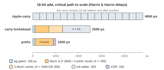
At 16 bits that is 100 + 600 + 3 × 200 + 4 × 300 = 2500 ps. In Demo 1: FFFF + 0001 every column propagates and only bit 0 generates, so the carry made in bit 0 is passed on by C4, C8, C12 and C16 one AND-OR each: S = 0x0000 with C16 = 1. With static timing the delay is the same for any data; the clock must allow for the worst case anyway.
Prefix adder
A prefix adder (Prefix adder tab, H&H Figure 5.7) goes further: it computes the carry into every bit with a tree. Write Gi:j and Pi:j for the generate and propagate of columns i down to j, and treat the carry in as column −1 with G−1:−1 = Cin, P−1:−1 = 0. Then Gi−1:−1 is exactly the carry into bit i, and
Two neighbouring spans combine like this, where k − 1 is the top of the lower span:
A black cell computes both G and P. A grey cell computes only G, because its span already reaches column −1 and nothing above needs its P. At level 1 spans of 1 bit combine into spans of 2, at level 2 into spans of 4, and so on: after log2N levels every column holds Gi:−1.
At 16 bits: 100 + 4 × 200 + 100 = 1000 ps. In Demo 2: 0FFF + C_in the carry in is 1 and bits 11..0 all propagate, so the 1 in column −1 reaches G11:−1 through grey cells and the sum is 0x1000. Bit 0 is valid at 200 ps (pg, then its XOR with Cin); bit 15 at 1000 ps.
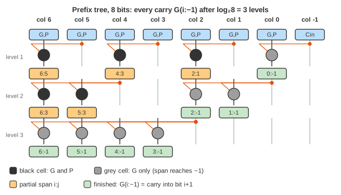
The tree drawn is the one in the book, a divide-and-conquer tree (Sklansky): few cells, but one cell can drive up to N/2 others. Kogge-Stone uses a cell in every column at every level so no cell drives more than two, at the cost of more cells and long wires; Brent-Kung uses about 2N cells but 2·log2N − 1 levels.
The race: 16 and 32 bits
The Adder race tab computes the same addition in all three adders and moves one clock across them (Demo 3: 16 bits, Demo 4: 32 bits). The bar under each adder is its critical path to scale, split into its delay parts.
| Adder | Delay formula | 16 bits | 32 bits |
|---|---|---|---|
| ripple-carry | N·tFA | 4800 ps | 9600 ps |
| carry-lookahead, k = 4 | tpg + tpg_block + (N/k − 1)tAND_OR + k·tFA | 2500 ps | 3300 ps |
| prefix | tpg + log2N·tpg_prefix + tXOR | 1000 ps | 1200 ps |
The 32-bit numbers are H&H Example 5.1. Doubling the width doubles the ripple delay, adds four AND-OR delays (800 ps) to the CLA, and adds one level (200 ps) to the prefix adder. Speed costs hardware: at 32 bits the prefix adder needs 33 pg cells, 80 black and grey cells and 32 XORs instead of 32 full adders.
Subtraction
In two's complement −B = NOT B + 1, so A − B = A + NOT B + 1. One adder does both: a sub signal goes to an XOR on every B bit (Bi ⊕ 1 = NOT Bi) and into the carry in (Subtract & compare tab, operation menu). This is the same trick as the Bnegate line of the ALU in the single-cycle MIPS processor.
Comparators and flags
An equality comparator needs no adder: XNOR each pair of bits (1 where they are equal) and AND the results. Here that takes 100 + 300 = 400 ps. A magnitude comparator computes A − B and looks at the result through four flags:
| Flag | Meaning | Logic |
|---|---|---|
| Z | result is zero | NOR of all result bits |
| N | result is negative | Y7, the sign bit |
| V | signed overflow: the true result does not fit | C7 ⊕ C8 (carry into and out of the sign bit differ) |
| C | carry out | C8; for A − B, C = 1 means no borrow |
| Question | From the flags of A − B |
|---|---|
| A = B | Z |
| A < B, signed | N ⊕ V |
| A < B, unsigned | NOT C |
Demo 5 first subtracts 77 − 77: Z = 1, and the XNOR comparator says equal at 400 ps, long before Z is valid at 2800 ps. Then −1 vs 1: the same bits are 0xFF and 0x01. Signed, −1 < 1 (N ⊕ V = 1); unsigned, 255 > 1 (C = 1, so NOT C = 0). The circuit is the same; only the question differs.
Just using the sign bit (H&H Figure 5.12 uses N for less-than) fails on overflow. In Demo 6: overflow, 100 − (−50) = 150 does not fit in 8 bits: Y = 0x96 = −106, so N = 1 says "A < B", which is wrong. V = 1, and N ⊕ V = 0 gives the right answer.
Shifters and rotators
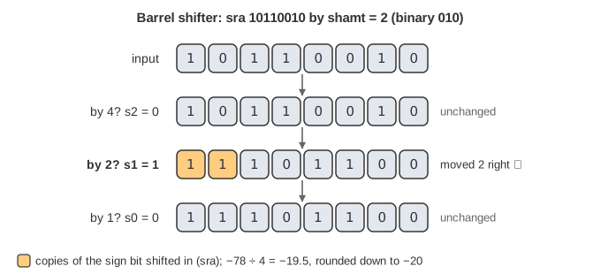
A shifter moves bits left or right by a shift amount shamt. A barrel shifter does it with log2N levels of 2:1 multiplexers (Shifter tab): the first level shifts by 4 if bit s2 of shamt is 1, the next by 2 if s1 is 1, the last by 1 if s0 is 1. Any amount from 0 to 7 is a sum of those, and every shift takes the same three mux delays. H&H draws an equivalent shifter from N N:1 multiplexers, one per output bit.
| Type | Bits shifted in | Arithmetic meaning |
|---|---|---|
| sll, shift left logical | 0 on the right | × 2shamt |
| srl, shift right logical | 0 on the left | unsigned ÷ 2shamt |
| sra, shift right arithmetic | copies of the sign bit | signed ÷ 2shamt, rounded down |
| ror, rotate right | the bits that fall out on the right | none: the same bits, rotated |
Demo 7 shifts 10110010 (−78 signed) right by 2: srl gives 00101100 = 44, sra gives 11101100 = −20, which is −78 ÷ 4 = −19.5 rounded down.
Array multiplier
Binary multiplication is long multiplication with digits 0 and 1. Each partial product is one bit of A times one bit of B, so it is an AND gate: a 4 × 4 multiplier has 16 of them. Row j holds A·Bj, shifted left by j. An array multiplier adds the rows with one row of adders per bit of B (Multiplier tab, H&H Figure 5.21): each row adds the next partial products to the upper bits of the row above, and the lowest bit of each row is a finished product bit. N-bit × N-bit gives a 2N-bit product.
Demo 8: 15 × 15 = 225 = 11100001. Its critical path is one AND and then 8 adder delays down and across the array: 100 + 8 × 300 = 2500 ps. Faster multipliers add the partial products with carry-save adders in a tree and use a fast adder only once at the end.
What the page leaves out
- Static timing only: the worst-case delay of every block, the same for any data. Real outputs can settle earlier, and can glitch on the way; the Combinational Logic page simulates that gate by gate.
- Contamination delay (the earliest an output can change), wire delay, fan-out loading: a Sklansky cell that drives 8 others is really slower than one that drives 2.
- The carry out of the prefix adder is computed (one more grey cell) but not drawn.
- Carry-select and carry-skip adders, carry-save addition, Booth and Wallace-tree multipliers, sequential shift-and-add multipliers, and division.
- Fixed-point and floating-point number formats and their arithmetic.
- How the clock period follows from the critical path, and pipelining a long path into stages: see Sequential Logic for setup time and maximum clock frequency.
References
Harris and Harris, Digital Design and Computer Architecture, 2nd ed., Section 5.2: Arithmetic Circuits (Example 5.1, Figures 5.6, 5.7, 5.12, 5.21)
Brent and Kung, "A Regular Layout for Parallel Adders", IEEE Transactions on Computers, 1982