The idea: a computer is nine levels of abstraction
A computer is far too complex to understand all at once. Engineers cope by abstraction: each level is described only by what it offers to the level above (its interface), and it hides how it does it. A C programmer uses + and never thinks about transistors. A logic designer uses gates and never thinks about electrons.
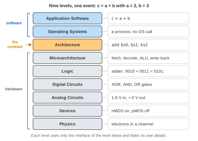
The page draws the nine levels from Harris and Harris (figure 1.1): Application Software, Operating Systems, Architecture, Microarchitecture, Logic, Digital Circuits, Analog Circuits, Devices and Physics. On the right it shows one concrete thing as it looks at the level you are on. Use Down ↓ and Up ↑, the level select, or Trace down to visit them. The strip under the canvas collects one short description per level you have visited: blue on the way down, green on the way back up.
It is a map, not a simulator. Each level has a page of its own on this site that goes much deeper; the table at the end lists them.
One statement, nine true descriptions
Follow c = a + b with a = 2 and b = 3 (c = a + b tab, Demo: all the way down). Every row of this table describes the same event:
| Level | What c = a + b is here |
|---|---|
| Application Software | a line of C: add two variables |
| Operating Systems | one instruction of a running process; the OS is not called |
| Architecture | add $s0, $s1, $s2, the 32-bit word 0x02328020 |
| Microarchitecture | fetch, decode and read registers, ALU adds, write back |
| Logic | a ripple-carry adder: 0010 + 0011 = 0101 |
| Digital Circuits | XOR, AND and OR gates of each full adder |
| Analog Circuits | voltages: 1.8 V in, about 0 V out of each inverter stage |
| Devices | nMOS transistors turn on, pMOS turn off |
| Physics | electrons drawn into a channel under each transistor's gate |
None of these is "the real one". Each is exact at its own level. Going back up (Demo: back up) shows how the result 5 climbs from a conducting channel to c = 5 on the screen.
Application software and the compiler
Programs are written in a high-level language. A compiler translates them into instructions of the architecture; a library (libc in C, the class library in Java) wraps the services of the OS. The compiler also decides where variables live: here it keeps a, b and c in the registers $s1, $s2 and $s0. See how a C program is compiled and linked and how a Java program is compiled and run.
The operating system: processes and system calls
The OS shares one machine among many programs. Each program runs as a process with its own virtual address space, and the scheduler gives it slices of CPU time. Most instructions, like the add, run directly on the CPU without the OS. The OS steps in only on an interrupt (for example the timer, which may switch to another process) or when the program asks it for something with a system call.
printf("hello world!\n") is such a case (printf tab). libc formats the 13 bytes into a buffer, then calls write(1, buf, 13). The syscall instruction switches the CPU to kernel mode; the kernel finds file descriptor 1 (the terminal), and passes the bytes to the pseudo-terminal driver, from which the terminal emulator reads and draws them. See also how Linux loads a program and virtual memory.
Architecture: the contract between software and hardware
The architecture, or instruction set architecture (ISA), is everything a programmer (or a compiler) must know to write correct machine code: the instructions, the registers and how memory is addressed. This page uses MIPS32. An add is an R-format instruction:
| Field | op | rs | rt | rd | shamt | funct |
|---|---|---|---|---|---|---|
| Bits | 6 | 5 | 5 | 5 | 5 | 6 |
| add $s0, $s1, $s2 | 000000 | 10001 (17) | 10010 (18) | 10000 (16) | 00000 | 100000 (32) |
Together: 0000 0010 0011 0010 1000 0000 0010 0000 = 0x02328020. A system call is the instruction syscall, with its number in $v0 (4004 for write on Linux MIPS o32) and its arguments in $a0–$a3.
Microarchitecture: one ISA, many designs
The microarchitecture is how one particular chip carries out the ISA: its datapath (registers, ALU, memories and the wires between them), its control unit, and tricks such as pipelining and caches. Different chips run the same machine code at different speeds and costs (One ISA, many chips tab). With Patterson and Hennessy's stage delays (IF 200, ID 100, EX 200, MEM 200, WB 100 ps), the four instructions add, sub, lw, or take:
| Design | Clock | Cycles | Time |
|---|---|---|---|
| Single-cycle | 800 ps (the slowest instruction, lw) | 4 | 3200 ps |
| Multicycle | 200 ps (the slowest stage) | 4 + 4 + 5 + 4 = 17 | 3400 ps |
| Pipelined | 200 ps | 4 + 4 = 8 | 1600 ps |
All three leave the same values in the registers: the program cannot tell which one ran it. A syscall is handled by the microarchitecture as an exception: it records the cause (ExcCode 8, Sys), saves the PC in EPC, jumps to the exception vector 0x80000180 and enters kernel mode. See the MIPS datapath, the MIPS pipeline and the CPU cache.
Logic and digital circuits
The datapath is built from logic blocks: adders, multiplexers (choose one input), decoders (select one line), registers and memories. Each block is built from gates, the digital circuits level, where every signal is exactly 0 or 1. The ALU's adder is a chain of full adders; one full adder is two XOR gates, two AND gates and an OR gate. A memory is an array of rows, a row decoder that picks one, and a column multiplexer that picks a byte. See combinational logic and sequential logic.
The digital abstraction: logic levels and noise margins
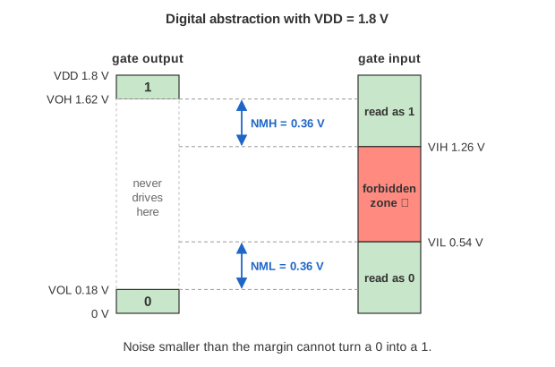
A wire really carries a voltage, any value between 0 and the supply VDD. The digital abstraction agrees to read low voltages as 0 and high ones as 1, with a forbidden zone between. A gate's output promises to be stronger than its input needs, so small noise cannot turn a 0 into a 1. With VDD = 1.8 V and the textbook thresholds used on the page:
| Level | Meaning | Value |
|---|---|---|
| VOL | highest output voltage for a 0 | 0.18 V |
| VIL | highest input voltage read as 0 | 0.54 V |
| VIH | lowest input voltage read as 1 | 1.26 V |
| VOH | lowest output voltage for a 1 | 1.62 V |
| NML, NMH | noise margins VIL − VOL, VOH − VIH | 0.36 V each |
Because every gate restores its output to near 0 V or near VDD, errors do not add up from gate to gate. This one idea is what lets every level above ignore physics.
Devices and physics: CMOS transistors
Gates are made of transistors. In CMOS, an nMOS transistor conducts when its gate is high and a pMOS when its gate is low. An inverter is one of each: a high input turns the nMOS on and pulls the output to ground. A NAND takes 4 transistors, a full adder about 28, a modern processor billions.
Why a voltage turns a transistor on is physics. Silicon doped with boron (p-type) has free holes; doped with phosphorus (n-type) it has free electrons. A positive voltage on the gate, across a very thin oxide, draws electrons into a thin channel between the source and the drain: the field effect. DRAM stores a bit as charge on a tiny capacitor next to a transistor; the charge leaks, so every row is refreshed at least every 64 ms.
When abstractions leak
An abstraction leaks when a detail it should hide shows through (Leaks tab):
- Integer overflow (Architecture → Application):
2147483647 + 1is 0x80000000, which as a 32-bit signed int is −2147483648. Java defines this wrap; in C it is undefined behaviour. - Cache order (Microarchitecture → Application): summing a large 2-D array column by column misses the cache on almost every access, so it is much slower than row by row, with the same instructions and the same answer.
- Rowhammer (Physics and Devices → OS): reading two DRAM rows very often drains charge from the row between them and can flip a bit nobody wrote. If that bit is in a page table, memory isolation breaks.
Others: 0.1 + 0.2 != 0.3 (binary floating point in the architecture), and Spectre (speculative execution in the microarchitecture leaks secrets through cache timing). The lesson: know at least the level below the one you work at.
Where to go deeper
| Level | Pages |
|---|---|
| Application Software | C Compile & Link, Java Compile |
| Operating Systems | Program Load, Context Switch, Virtual Memory, Interrupt I/O |
| Architecture, Microarchitecture | MIPS Datapath, MIPS Pipeline, CPU Cache |
| Logic, Digital Circuits | Combinational Logic, Sequential Logic |
| Analog Circuits, Devices, Physics | this page only (the sections above) |
What the page leaves out
Real processors are x86-64 or ARM, out of order and superscalar, with several cache levels; this page uses the textbook MIPS. The compiler's optimisations, the dynamic linker and the terminal's rendering are skipped. The voltages (VDD = 1.8 V, the thresholds, the sense-amplifier swing) and the DRAM retention curve are illustrative textbook values, not those of one real chip. The cache example is a tiny model. Each level is reduced to one picture; the linked pages go further.
References
Harris and Harris, Digital Design and Computer Architecture, chapter 1 (managing complexity, the digital abstraction, logic levels, CMOS transistors)
Patterson and Hennessy, Computer Organization and Design, chapter 1 (below your program) and chapter 4 (the processor: single-cycle and pipelined datapaths)
Kim et al., Flipping Bits in Memory Without Accessing Them (ISCA 2014): the Rowhammer paper